Product: ABAQUS/Standard
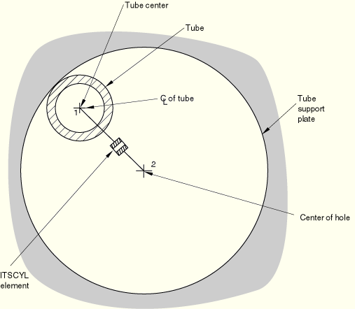
These elements are provided for the specific case of modeling the interaction between a tube and a support that is not always in contact with the tube during dynamic events. The tube is assumed to have a circular section and can interact with one of two tube support geometries: a circular hole and an “egg-crate” support. Two interface elements of this type are provided, one for each geometry, as shown in Figure 3.9.4–1 and Figure 3.9.4–2. As indicated in Figure 3.9.4–2, one cylindrical geometry interface is needed to model the interaction of the tube with a circular hole, while Figure 3.9.4–1 shows that several unidirectional geometry elements are needed to model the interaction with an egg-crate—one element perpendicular to each pair of egg-crate faces.
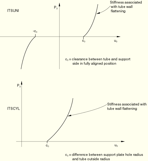
The interface elements themselves consist of a spring and friction link and a dashpot, as shown in Figure 3.9.4–3. The spring is assumed to behave as shown in Figure 3.9.4–4: when there is no contact between the tube and the support, no force is transmitted by the spring; when the tube is in contact with the support, the force increases as the tube wall is deformed. This force can be modeled as a linear or a nonlinear function of the relative displacement between the axis of the tube and the center of the hole in the support.
The frictional part of the spring and friction link uses the Coulomb friction model in ABAQUS: that model is described in “Coulomb friction,” Section 5.2.3.
The dashpot is provided to model fluid effects in the annulus between the tube and the support plate. Its behavior can be linear or nonlinear. The model assumes that shear forces created by the fluid are negligible, so that the only shear forces transmitted by one of these interface elements are the frictional forces caused by direct contact between the tube and the support.
A major simplification in these elements that saves considerable computational effort in dynamic applications is the assumption that impacts between the tube and its support plates involve no instantaneous transfer of momentum or energy loss: the standard impact algorithm of ABAQUS/Standard used with gap and other interface elements (and described in “Intermittent contact/impact,” Section 2.4.2) is not needed. This simplification derives from the assumption that these elements will be used in conjunction with beam element models of the tube, so the tube section is defined by the position and orientation of its axis and local deformation of the cross-section of the tube is neglected. In reality, when the tube hits a support, initially only a small part of the tube wall loses momentum so that there is—instantaneously—only a small loss of kinetic energy. This instantaneous energy loss is neglected when these elements are used. The subsequent flattening of the tube wall is modeled by the spring link in the element, acting between the node on the tube axis and the node representing the center of the hole. Thus, the modeling of this local flattening behavior as an equivalent spring provides the simplification that instantaneous impact calculations are not needed. In cases where this approach is not reasonable, gap elements can be used instead of these special interface elements, at the cost of more computational effort.
The remainder of this section discusses the kinematic definitions used in these elements and their contributions to the overall equilibrium equations and to the Jacobian (stiffness) matrix needed in the Newton solution of those equations.
Each tube support element has two nodes. One node represents the axis of the tube, the other is the center of the hole in the support plate (or midway between a pair of parallel sides of an “egg-crate”).
Let ![]() be a unit vector along the axis of the tube, and let
be a unit vector along the axis of the tube, and let ![]() be a unit vector along the axis of the interface element (that is, perpendicular to the parallel sides of the support in the “unidirectional” interface that is used with egg-crate supports, and parallel to the line joining the two nodes of the element in the “cylindrical” interface that is used with circular holes). It is assumed that
be a unit vector along the axis of the interface element (that is, perpendicular to the parallel sides of the support in the “unidirectional” interface that is used with egg-crate supports, and parallel to the line joining the two nodes of the element in the “cylindrical” interface that is used with circular holes). It is assumed that ![]() is in the cross-section of the tube and, hence, orthogonal to
is in the cross-section of the tube and, hence, orthogonal to ![]() . We define a third basis vector as
. We define a third basis vector as
![]()
Let ![]() be the current position of node
be the current position of node ![]() of the element at any point in time (here
of the element at any point in time (here ![]() is 1 or 2).
is 1 or 2).
Relative displacements in the element are measured from the position when the tube and the hole in the support plate are exactly aligned; that is, when the nodes of the element are at the same location. They are defined as follows:
axial to the interface element,
![]()
axial to the tube,
![]()
tangential, in the plane of the tube's cross-section,
for the unidirectional case:
![]()
and, for the cylindrical case:
![]()
The basis vector—![]() , along the axis of the tube and of the hole in the support plate—is assumed to be fixed. In the unidirectional element the
, along the axis of the tube and of the hole in the support plate—is assumed to be fixed. In the unidirectional element the ![]() and
and ![]() vectors are also fixed. In the cylindrical interface
vectors are also fixed. In the cylindrical interface ![]() is parallel to the line joining the nodes of the element, so
is parallel to the line joining the nodes of the element, so
![]()
![]()
![]()
Thus, for this element
![]()
![]()
For simplicity we replace the integral with the backward difference approximation
![]()
The element generates an axial force—![]() , parallel to
, parallel to ![]() —and two shear forces—
—and two shear forces—![]() , parallel to
, parallel to ![]() and
and ![]() , parallel to
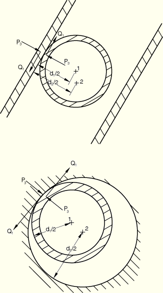
, parallel to ![]() . In addition, because the nodes of the element are at the center of the tube and at the center of the hole in the support, while the interaction forces between the tube and its support are transmitted at the point of contact of the tube with the support, these forces also cause moments at the nodes of the element. It is assumed that the moments caused by
. In addition, because the nodes of the element are at the center of the tube and at the center of the hole in the support, while the interaction forces between the tube and its support are transmitted at the point of contact of the tube with the support, these forces also cause moments at the nodes of the element. It is assumed that the moments caused by ![]() and by
and by ![]() are not significant and can be neglected. The only moments considered are
are not significant and can be neglected. The only moments considered are ![]() at node 1, the center of the tube, and
at node 1, the center of the tube, and ![]() at node 2, the center of the hole. Here
at node 2, the center of the hole. Here ![]() is the outside diameter of the tube and
is the outside diameter of the tube and ![]() is the diameter of the hole for the cylindrical interface or is the distance between the parallel support plates for the uniaxial interface (see Figure 3.9.4–5).
is the diameter of the hole for the cylindrical interface or is the distance between the parallel support plates for the uniaxial interface (see Figure 3.9.4–5).
The virtual work contribution of the element is, then,
![]()
From this expression the contribution of the element to the Jacobian (stiffness) matrix of the equilibrium equations is immediately available as

The “initial stress” terms,
![]()
![]()
![]()
![]()
![]()
![]()
The “initial stress” terms for the cylindrical interface are, therefore,
The other terms in the stiffness matrix are associated with changes in the forces in the element, ![]() ,
, ![]() , and
, and ![]() . We assume
. We assume ![]() is made up of a spring force that is a function of
is made up of a spring force that is a function of ![]() and a dashpot force that is a function of
and a dashpot force that is a function of ![]() :
:
![]()
![]()
![]()
For the implicit integration operator used for nonlinear dynamic analysis in ABAQUS/Standard,
![]()
![]()
Thus,
![]()
The values of ![]() and
and ![]() come from the friction theory and are defined from
come from the friction theory and are defined from ![]() ,
, ![]() , and
, and ![]() by that theory (see “Coulomb friction,” Section 5.2.3).
by that theory (see “Coulomb friction,” Section 5.2.3).
In summary,
![]()
![]()
This matrix is not symmetric if ![]() ,
, ![]() , or
, or ![]() is nonzero. Without friction they are zero, and the terms in
is nonzero. Without friction they are zero, and the terms in ![]() and
and ![]() are the only nonzero terms. With relatively small friction coefficients in dynamic applications the terms
are the only nonzero terms. With relatively small friction coefficients in dynamic applications the terms ![]() and—if the tube diameter is not very large—
and—if the tube diameter is not very large—![]() ,
, ![]() ,
, ![]() and
and ![]() can be neglected and, thus, a symmetric approximation to the Jacobian matrix used without serious degradation of the convergence rate of the Newton solution of the equilibrium equations.
can be neglected and, thus, a symmetric approximation to the Jacobian matrix used without serious degradation of the convergence rate of the Newton solution of the equilibrium equations.