Product: ABAQUS/Standard
Frame elements admit an optional force response in which axial force only is supported by the element. Furthermore, the axial force is constant along the element; all transverse forces and all moments in the element are zero. The axial forces in the element may be linear elastic or may admit a buckling strut response where the force versus axial strain is characterized by a buckling envelope with hysteresis, as described below. For details on the standard frame element response, see “Frame elements with lumped plasticity,” Section 3.9.2.
In compression the buckling strut response models, in a simple way, the highly nonlinear buckling and postbuckling damage of slender members when loaded monotonically or cyclically. In tension the response is modeled by isotropic hardening plasticity. The buckling strut envelope is phenomenological, derived from experiments with pipe-like members. Since the description of the buckling envelope includes the outer pipe diameter and the pipe thickness, only pipe cross-section types are permitted with buckling strut response.
The buckling strut response is linear elastic until the compressive loading exceeds ![]() , the critical load to cause buckling. The value of
, the critical load to cause buckling. The value of ![]() is determined with the ISO (International Organization for Standardization) equation, as described below.
is determined with the ISO (International Organization for Standardization) equation, as described below.
The ISO equation is used to predict the onset of buckling in slender members with pipe-like cross-sections. All quantities with dimensions have dimensions of stress. We define ![]() , which is a function of the axial compressive stress,
, which is a function of the axial compressive stress, ![]() , and the maximum bending stresses about the local
, and the maximum bending stresses about the local ![]() and
and ![]() axes,
axes, ![]() and
and ![]() , by the expression
, by the expression
![]()
![]()
is the yield stress,
![]()
is Young's modulus of elasticity,
![]()
is the cross-sectional area,
![]()
are the effective length factors in the 1- and 2-directions (user-defined),
![]()
are the unbraced lengths for the 1- and 2-directions (user-defined),
![]()
are the bending moments of inertia about the local cross-section directions,
![]()
is the elastic section modulus,
![]()
is the plastic section modulus,
![]()
is the radius of gyration.
![]()
![]() ,
,
![]()
![]() ,
,
![]()
![]() ,
,
![]()
![]() .
.
![]()
is the axial compressive stress, ![]() with
with ![]() the axial force in the element.
the axial force in the element.
![]()
are the maximum bending stresses about the 1 or 2 cross-section axis,
![]() ,
, ![]() with
with ![]() and
and ![]()
the bending moments about the 1 and 2 direction.
![]()
is the characteristic local buckling stress,
![]() for
for ![]() ,
,
![]() for
for ![]() , where
, where ![]() and
and
![]() ,
,
![]() for
for ![]() ,
,
![]() ,
,
![]() is a critical buckling coefficient.
is a critical buckling coefficient.
![]()
is the characteristic axial compressive stress,
![]() for
for ![]() ,
,
![]() for
for ![]() , where
, where ![]() ,
,
with ![]() ,
,
![]() .
.
![]()
is the characteristic bending stress (for pipe sections ![]() ),
),
![]() for
for ![]() ,
,
![]() for
for ![]() ,
,
![]() for
for ![]() ,
,
where ![]() and
and ![]() .
.
![]()
are Euler buckling stresses corresponding to the 1 or 2 directions,
![]() and
and ![]() .
.
![]()
are reduction factors corresponding to the cross-section directions 1 and 2, respectively. These factors are user-defined as functions of the end moments, compression stress, and Euler buckling stresses. The default value for each factor is ![]() .
.
If switching between standard frame element response and buckling strut response is permitted, the one-time-only switch to buckling strut response occurs when ![]() . The ISO equation provides the value of critical load,
. The ISO equation provides the value of critical load, ![]() , which is defined as the value of axial force
, which is defined as the value of axial force ![]() in the element when the ISO equation is satisfied. To prevent switching in cases where negligible axial force exists with large bending moments, an additional inequality is used. This additional check, called the strength equation, takes the following form:
in the element when the ISO equation is satisfied. To prevent switching in cases where negligible axial force exists with large bending moments, an additional inequality is used. This additional check, called the strength equation, takes the following form:
![]()
![]()
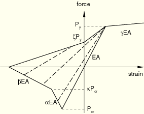
The Marshall strut envelope defines the postbuckling damaged elasticity model and the hysteretic loop response. To define the Marshall strut envelope, the value of ![]() and the following seven constants are needed:
and the following seven constants are needed:
![]()
is the coefficient defining ![]() (
(![]() ),
),
![]()
is the isotropic hardening slope coefficient (0.02),
![]()
is the coefficient defining ![]() , (
, (![]() ),
),
![]()
is the coefficient defining ![]() , (
, (![]() ),
),
![]()
is the force coefficient (0.28),
![]()
is the slope coefficient (0.02), and
![]()
is the force coefficient (min(1.0, ![]() )).
)).
The values in parentheses are the default values supplied by ABAQUS, and the value of ![]() is found from the ISO equation as explained above.
is found from the ISO equation as explained above.
The Marshall envelope governs the compressive and tensile response of the strut as shown in Figure 3.9.3–1. The dotted lines in the interior of the envelope indicate the damaged-elastic modulus defining the loading-unloading force versus strain path.