Searching for Stability Weekly Log
Contents
2/13/16
This week we successfully scaled down our initial project idea for a quadcopter to a more feasible product idea of an Arduino controlled 2-axis gimbal on a bike-mounted platform. As opposed to using an IMU, we decided to use two magnetic rotary encoders to challenge ourselves in the realm of electrical and systems engineering. Additionally, we finalized a project proposal after making some intensive revisions and created a detailed budget.
We have conducted initial research concerning the connection of the rotary magnetic encoders to the Arduino.
2/20/16
We completed a first design rendering for our stabilization platform; it is in the very early stages of development.

Components

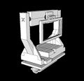
Assembled Design 1


This was the second version we designed later in the week. It illustrates how the iPhone would sit in the gimbal and where our two motors would be located.
.jpg)

We were concerned that this mounting design would be impractical for a bike-rider as the gimbal would take up the entirety of one handle. However, after some research, we found that the majority of bike mounted devices sit on the handlebar and thus plan to model a revised design after pre-existing handlebar bike mounts. Additionally, we are including more specific compartments within the back slot housing the four 9V batteries and the Arduino to eliminate unnecessary confusion and jumbling of components.
In addition to these designs, we ordered our magnetic rotary encoders and vibration dampening pads and plan to order the batteries and motors once the budget is approved.
2/27/16
Our budget was approved! We ordered two Turnigy brushless gimbal motors and four rechargeable 9V batteries. Our encoders and vibration dampening pads arrived on Wednesday, however we got two extra relay boards while the two rotary encoder shafts were omitted from the shipment. We called the vendor and the missing components were expedited to us and arrived on Saturday.
We continued to update the 3D design of our mounting platform, altering the housing of the Arduino so that it would sit under the gimbal but above the dampening pads and adding a tray for the batteries instead of a back pocket. We began test printing on Friday. We printed the two basic components that attach directly to the bike handle and tested to make sure the dimensions were correct and that they fit together snuggly. While the first print failed due to the presence of internal faces, we re-printed after fixing the file and the dimensions appeared correct when tested for fit on a bike handle. The first print of the outer support component also failed due internal faces that confused the printer. From this failed print, however, we realized that some of the proportions were off as the Arduino could not fit in its designated compartment. Thus, we altered the design to make the compartment sufficiently tall and added some structural support to the two arms of the outer frame. After printing a miniature version to ensure that there were no more internal edges, we initiated a full-sized print of the outer frame. Below are images of the mounting device with the revised frame structure, the miniature print of the outer frame, and the two basic components for direct mounting on the bike.
Updated Design

3D Print of Direct Bike Mount

Miniature Print of Outer Support


With regards to programming the Arduino, progress has been relatively slow as we both are unfamiliar with the coding language. Natalie successfully downloaded the Arduino software (IDE) to her computer and uploaded and ran the "Blink Example". We are working hard to research how to go about writing code that will receive input from the encoders regarding the position of the motors and output corrections to the motor. Additionally, we are in the process of devising test cases so that we can test our code or portions of code without having to have a fully functional mechanical model.
3/5/16
This week we printed a preliminary phone case and the attachment mechanism for the case to the gimbal. We received our two gimbal motors in the mail but have yet to plug them into anything to see what they do our what kind of output they give. We had a productive first evaluation with Deko and Professor Humberto and determined where we need to direct our focus. Figuring out how to secure wires on moving parts will be a challenge, as will be designing the control program for the Arduino. I (Natalie) need to learn how to write interrupts.
Professor Humberto also told us that he did not expect us to be able to pull off our entire goal by the end of the semester. We need to focus on being able to get any corrective motion, no matter what speed, from the gimbal.
3/26/16
After struggling to make progress with writing Arduino code and not having had time to mess around with our ordered parts, we were finally able to get into lab for a substantial period of time. We had a meeting with Deko and we were able to control a motor (fan) with an Arduino Uno and a motor shield. However, we were unable to do the same for our gimbal motors and believe we might need a motor driver in order to do so.
After some research, we determined that we probably do not need the Hall sensors that came with our magnetic rotary encoders to generate the output we want, though they might give us better data once we have everything set up correctly. Using a tutorial and a schematic we found on hobbytronics.com, we built a circuit using an Arduino Uno and a motor shield to attempt to control the encoders. The code was meant to change the brightness of an LED according to the angle of the rotary encoder. While we got the LED to light up, we ran into trouble because no matter which way we turned the encoder, the brightness value either continued to increase or, if we changed the code, continued to decrease. Therefore the position of the rotary encoder was unable to dictate brightness according to clockwise v. counter-clockwise direction... a significant problem considering the objective of our project. The circuit we used is pictured below:

While we ran out of time to continue trouble-shooting, we have set aside time in the upcoming week to continue figuring out both components: the encoders and the motors. Our to-do list is as follows:
- Research driver for our BLDC gimbal motor
- Figure out encoder code that will account for clockwise v. counter-clockwise motion
- Find detailed schematics concerning the mounting of the rotary encoder
In addition to the circuitry/coding work that we did, we also assembled the base of our gimbal mount.


4/2/16
On Wednesday we successfully gained control over both a gimbal motor and a rotary encoder. Previously we had struggled to get the encoder to register the difference between clockwise and counter-clockwise rotation. I (Natalie) focused on finding out how to address this issue. At first, I thought it would possible to treat the rotary encoder as a potentiometer. However, while both have three pins, they serve different purposes. The potentiometer has one for ground, one for signal, and one for power. On the other hand, the rotary encoder has two for signal/code and one for ground. Based on this information, the circuit including just the rotary encoder was simple. Wires led from the encoder to pins 2 and 3 on the Arduino Uno and one wire led to ground on the Arduino.

The key to operating the encoder is the fact that there are four possible output states (00, 01, 10, 11). Depending on the order of these states, the encoder is either rotating clockwise or counterclockwise. We need to keep track of these states at all times so that we can discern rotation and whether the order/direction of rotation changes. This requires the use of interrupts. I was able to find a sample sketch on bildr.org and, by serial printing the encoder value, I was able to get the value to increase when the encoder was rotated clockwise and decrease when rotated counterclockwise. This code generates integer values that correspond to the position of the encoder. They can be negative or positive depending on whether the encoder is going clockwise or counterclockwise past zero and they have no max or min values unless they are explicitly set. The next step with the encoders is to try and get communication between an encoder and a motor.
Nathan focused on the motor. Previously, we had been unable to get the motor respond to the Arduino. Using code derived from a YouTube video (Arduino simple 3-phase brushless (tarot GoPro gimbal) without ESC/MotorDrive), Nathan was able to get our motor to spin. After some modification, he was able to change the direction of spin. Given that we do not have ESCs (Electronic Speed Controllers) to control the 3-phase brushless motors, the code provides three pulsing voltages to the three different phases of the motor respectively. The offset times of these three pulses had to be tuned so that each pulse propelled the motor into the next phase. Making small changes in the offset times corresponded to changes in the revolution speed of the motor. Finally, reversing the order of the pulses caused a reverse in the direction of the rotation of the motor.
The setup for the motor is as depicted:


On Friday, I (Natalie) was able to get some communication between our rotary encoder and Deko's DC motor fan. This required creating an long array of length two that would hold the previous value of the encoder and the present value of the encoder so that the two values could be compared outside of the interrupt. This was done in the loop so that the values in the array were shifted every time the loop ran. First, I created a boolean didChange and printed to see whether the program could register when the encoder value changed. Once this worked, I wrote code to incorporate the motor so that if didChange was true, the motor would turn on. Using this code I managed to establish communication between the motor and encoder. The next step was to get the motor to turn one way if the previous encoder value was larger than the present and the other way if the opposite was true. Unfortunately, we realized that Deko's motor could only turn in one direction so I would need to continue programming with our gimbal motors, whose code was complex and still in the works.
Nathan completed a second print of the main frame of the phone mount with some alterations meant to take into account the wiring.


After examining the print, we decided that there were a number of changes that needed to be made to give the mount the functionality it needed.
- The attached tube meant to hold wires needed to be eliminated and replaced with half-rings to give easier access and visibility
- The lip holding in the Arduino needed to be lowered so that there would be easier accessibility to the housing
- The battery trough needed to be widened so that we could fit all four batteries without having them slide around
- The roofing on the Arduino housing needed to be removed so that we would have easier access when wiring and could see if any disconnects were to occur during movement of the gimbal. We also decided to add a removable cap to the housing instead of a permanent roof so that we could close off the chamber once the wiring was secure.
The design was fixed and prepared for printing, though we would have to do a miniature print to make sure all the changes would work out without wasting both time and material.
After assembling a motor to the second version of the main frame, Nathan had to adjust the motor code in order to account for the weight that the motor was now responsible for turning. This required increasing the minimum speed in between each pulse from 7 milliseconds to 13 milliseconds. He was then able to get the rotating bar to "tick" using the motor, however we noticed the ticks were uneven based on the weight distribution of the bar and how it was positioned in the rotation. He was also able to smooth out the rotation of the bar, however the code was becoming cumbersome and Deko encouraged him to try a different way of coding the three pulses using a cosine wave and phasors to clean up the code.
On Saturday we printed the cover for the Arduino housing and printed some miniature versions of our main frame. The first mini-frame printed ok, however one of the holes we added to account for wires still had a face so we needed to fix the design and print a second mini. In the second mini we discovered new internal edges that needed to be removed. After a successful third mini, we began the full-sized print.
Additionally we figured out the equations for the phasors, except instead of using 1/2 we would be using 255/2 to account for the full range of pwm.

Unfortunately, we have been unable to generate smooth rotation using the algorithmic code. We're unsure as to whether this is due to Arduino's ability to handle equations or the actual implementation of the code itself. While the phasor code is pending, I worked on establishing communication between one of our rotary encoders and a gimbal motor. Using the more cumbersome code that works well despite being repetitive, I was able to get the motor to turn one way if the encoder was turned to the right and the other if it was turned to the left...exciting!!!

The next step will be to implement this code with the additional encoder and motor to make sure that we can run pairs simultaneously. Once this has been established, we will have to map an encoder value to an angle on the motor. It seems that the encoder is more sensitive than we initially thought -- for every "tick" of the encoder that we can feel, it counts 4 ticks on the Serial port so we will probably make one tick of the motor equivalent to four ticks on the encoder. How we implement the mapping will depend on whether or not we can get the phasor code to work or if we need to adapt the cumbersome code.
4/9/16
On Sunday, I (Natalie) edited the code to incorporate the second motor and encoder; the setup is depicted below. I managed to get distinct communication between "encoder1" and "motor1" and between "encoder2" and "motor2."


Tuesday was a frustrating day. After trying to run both motors simultaneously, it appears that while one is responding to the encoder, the other must wait for this response to finish before responding to its own encoder. While this is not ideal, it's not a deal breaker. I may spend some time looking to see if there might be a work-around to this but, as the code in response to the interrupts is linear, it seems unlikely. I worked on "ticks" and getting the motor response to correlate to the amount the encoder physically turned. While I was able to format some code Nathan developed into an array and generate a fairly decent response, the motors are shaky when the changes they respond to are too small. They seem to get stuck until there is a larger change that pushes them out of the rut. I'm not sure if smoothing out the response comes down to debouncing, but it will require further research and experimentation.
In addition to working on the code for the motors, Nathan continued to work on the gimbal design. As we have been able to think more concretely about the wiring needs of the gimbal, it has become apparent that the design must become increasingly complicated to accommodate all the functions necessary. Paramount among the current issues is balancing the phone in the mount. When we load the phone into the mount as designed, its weight causes it to fall face down instead of staying upright, completely defeating the purpose of the mount. Nathan redesigned the paddle in an attempt to keep the phone along the axis of spin as opposed to in front of it in order to give it more stability. Additionally, we have decided to mount the phone from a center-backed case as opposed to one that attaches to the top edge of the phone in an attempt to center the weight as much as possible. Our main challenges appear to be the lack of balance within the mount and the difficulty the motors have with turning evenly given unevenly distributed weight.
On Wednesday, Professor Humberto told us that the fact that we were getting any motor control at all was pretty much luck, because our circuit was not sending the current or the voltage to the motor that we thought it was; hence why it struggled when any weight was added because there was little to no torque behind the rotation. In Professor Humberto's words, it's a miracle we didn't fry anything. He gave us a new circuit to try to implement involving three transistors. The schematic is as depicted below. Nathan built the circuit on Thursday and it seemed to work, giving us more torque from the motor than we had felt before. However, when we attempted to build a second circuit for the second motor on Sunday, the circuit seemed to fry our board. We have scheduled a meeting with Deko for Tuesday to see where we went wrong.


In addition to the circuitry, Nathan printed a new paddle for the gimbal in an attempt to balance the phone. The first attempt placed the phone on the axis of spin but restricted the second axis of movement. The second is pictured below, with makeshift counterweights (table feet).


4/16/16
On Tuesday, we met with Deko so that he could review our circuit and make sure we didn't fry our new Arduino Mega. We determined that the cause of the fry was leaving the Arduino plugged directly into the breadboard and its power source, which allowed a backflow of voltage to the Arduino that was beyond what the board was capable of handling when the motor was not running. We were able to get the original circuit to power the motor as it had last Thursday without damaging the Arduino and then worked on the duplicate circuit. After checking resistances, we realized that two of the three transistors on the second circuit were faulty. Once we replaced these, both circuits were able to power a motor. Before beginning to solder, we wanted to see if the new circuit had improved torque enough to rotate unequally distributed weight.
We realized that getting the motors to rotate the weight would be a matter of getting the appropriate initial torque. Without this, the motor would never be able to pull out of a phase to rotate. By changing the delay time on the code to 28ms, we were able to get the motor to rotate the phone, a huge improvement!

Later in the week, we soldered all components of both motor control circuits to a proto-board and tested functionality to make sure both circuits were working. Both circuits were able to turn the motor. Occasionally we have issues with one of the transistors heating up and we're not sure why or what causes it because it's generally not the same transistor.

Natalie was able to get communication between the motor and encoder in both directions. While this is encouraging, we realize that the next big task is fine-tuning the response of the motor so that is comparable to the response in the encoder. At this point, the ticks of the motor are much larger than those of the encoder, causing the motor to over-compensate for any signal from the encoder.
Because our battery charger stopped functioning, we built an impromptu battery charger using a left over proto board that seems to be working.
Next steps
- fine-tune motor response
- encoder housing
- wiring and final setup/3D printing
4/23/16
Printed final version of mounting frame with housing for encoder and tested running the wires through the mount. Our battery charger became unreliable weeks ago and last week it stopped working completely. One by one our batteries have begun to fail. Despite ordering new, higher quality batteries, we have discussed with Deko and believe that for the hour-long demo next Thursday it will be necessary to use a power supply.
In regards to coding we determined that there are 78 ticks of the encoder per rotation and 42 iterations of the pulse arrays per motor rotation. This gives us a ratio of 78/42 for coding but, as our inputs to the motors must be integers, we will have to round to 2 and our results may be slightly off.
On Friday we met with Deko to discuss the use of the power supply and our transistors heating up. We had had trouble getting any response using the power supply even when we were getting reliable responses while using our batteries. After two hours of fiddling with the supply, we were able to get what seemed to be a reliable response from our motors using the supply; however Deko still recommended we pick up resistors with higher power rating.
4/30/16
The beginning of the week was a frustrating roller coaster of ups and downs. We went to RadioShack to get 6 10 watt, 10 ohm resistors because we thought it would help prevent our transistors from heating up. This meant pulling off 30 resistors from our proto board to replace them with the new big boys. Our circuit thus became an ethereal hellish jelly fish.

As we could have predicted judging from the rest of the semester, the power supply that we thought we had figured out last week ended up giving us trouble. We would spend 45 minutes fiddling and finding settings on the power supply and in the code that would generate rotation, only to pause for a few minutes or to turn in for the day and return to the same settings and find that they generated little to no response from our motors. This was particularly frustrating because getting communication between motor and encoder hinged upon a reliable response from the motors.
On Wednesday we had an emergency meeting with Humberto, worried that the demo was fast approaching and we had yet to gain reliable motor control. He explained to us that the nature of our problem was in the code. We needed to rewrite the code to PWM output in order to control three variables:
- motor frequency
- PWM frequency
- duty cycle
We spent the rest of Wednesday night re-writing and fine-tuning this code. We used arrays that were to send a sinusoidal output, only to be told at the demo that, while the output needed by our motors looks like a sinusoid, it isn't a true sinusoidal wave. By 2:30am Wednesday night, we thought we had it all figured out. We had rewritten our code and, as we have countless times this semester, seemed to have reliable control over our motors.


.gif)
We came back Thursday morning intending to finish up the project by cleaning up the encoder-motor connection, only to find that the code and settings on the power supply that we had been so confident in the night before no longer worked. Needless to say, we were greatly disappointed and spent the majority of the demo fiddling with code and settings only to generate small vibrations in our motors.