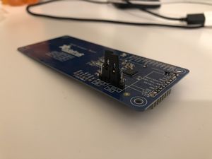
Particle photon setup with PN532 NFC board
Jump to navigation
Jump to search
Introduction
This tutorial will come in handy if you'd like to improve on the design found in the NFC Lock (link) project or just want to use NFC with your Photon. It shows how to set up the PN532 Breakout Board with the Particle Photon microcontroller so that you can - for example - lock or unlock a door through a servo if an NFC card is present.
What You Need
- Particle Photon Microcontroller and breadboard
- PN532 Breakout Board Kit (link) - this kit also includes everything you need to get the board soldered with headers, the 4050 shifter kit, and a NFC card
Board Setup
- Solder a strip of 8 header pins onto the narrow side of the breakout board
- Solder two strips of 3 header pins onto the SEL0 and SEL1 selector switches on the breakout board
- Set the two jumper blocks on the SEL0 and SEL1 pins so that SPI is selected (see pic for reference; SEL0 should be OFF, SEL1 should be ON)
Photon Setup
- Follow the setup instructions here to get your Photon running and connected to the internet.
Wiring
- Follow the wiring diagram on this page to get your Photon wired to the NFC board. The wiring will be the same except for the pins: 4050 pin 9 is connected to Photon A2, 4050 pin 11 is connected to Photon A3, MISO is connected to Photon A4, and 4050 pin 14 is connected to Photon A5.
Code
- With the Photon plugged into your computer via USB port, navigate to build.particle.io.build and type an app name in the text box on the upper left to start a new project. Press Enter to create it.
- Click the "Libraries" icon on the left sidebar (looks like bookmark) and search for Adafruit_PN532. Click on the result (there should be only one), click "Include in Project", and click your new app.
- Copy and paste this code into the main window:
// This #include statement was automatically added by the Particle IDE.
#include "Adafruit_PN532.h"

const int SS_PIN = A2;
const int SCK_PIN = A3;
const int MISO_PIN = A4;
const int MOSI_PIN = A5;

// note: these are not used for SPI mode
const int IRQ_PIN = A0;
const int RST_PIN = A1;

// set to SPI or I2C depending on how the header file is configured
#if PN532_MODE == PN532_SPI_MODE
  Adafruit_PN532 nfc(SCK_PIN, MISO_PIN, MOSI_PIN, SS_PIN);
#elif PN532_MODE == PN532_I2C_MODE
  Adafruit_PN532 nfc(IRQ_PIN, RST_PIN);
#endif

void setup() {
    nfc.begin();

    uint32_t versiondata;

    do {
        versiondata = nfc.getFirmwareVersion();
        if (!versiondata) {
            Serial.println("no board");
            delay(1000);
        }
    }
    while (!versiondata);

    Serial.print("Found chip PN5");
    Serial.println((versiondata>>24) & 0xFF, HEX);
    Serial.print("Firmware ver. ");
    Serial.print((versiondata>>16) & 0xFF, DEC);
    Serial.print('.');
    Serial.println((versiondata>>8) & 0xFF, DEC);

    // configure board to read RFID tags
    nfc.SAMConfig();

    Serial.println("Waiting for an ISO14443A Card ...");
}

void loop() {
    uint8_t success = 0;
    uint8_t uid[] = { 0, 0, 0, 0, 0, 0, 0 };  // Buffer to store the returned UID
    uint8_t uidLength = 0;                        // Length of the UID (4 or 7 bytes depending on ISO14443A card type)
    success = nfc.readPassiveTargetID(PN532_MIFARE_ISO14443A, &uid[0], &uidLength);

    if (success) {
        // Display some basic information about the card
        Serial.println("Found an ISO14443A card");
        Serial.print("  UID Length: ");Serial.print(uidLength, DEC);Serial.println(" bytes");
        Serial.print("  UID Value: ");
        nfc.PrintHex(uid, uidLength);

        if (uidLength == 4) {
            uint32_t cardid = uid[0];
            cardid <<= 8;
            cardid |= uid[1];
            cardid <<= 8;
            cardid |= uid[2];
            cardid <<= 8;
            cardid |= uid[3];
            Serial.print("Mifare Classic card #");
            Serial.println(cardid);
        }

        Serial.println("");
    }
}
Final Steps
- Click the lightning icon in the upper left hand of the editor - this will flash the code to your Photon. Wait for the Photon's LED to pulse blue before continuing on to the next step.
- Make sure the red light on the PN532 breakout board is red; if it's not, check your wiring and header soldering.
- Open up the Arduino app on your computer, make sure the right USB port is selected, and open the console window. It should be blank besides potentially a print statement detailing some stuff about the PN532 board.
- Wave the included NFC card over the NFC reader and check the console output. Congrats - you're done!
