Gravicase
Contents
Project Overview
Computers, tablets, smartphones: each cost hundreds of dollars. We buy them for their sleek designs, fluid screens and smooth buttons. Then, in order to protect them, we seal them away in big bulky cases, trapping our meticulously crafted phones or computers behind sturdy yet cumbersome plastic while we cover the vibrant screens with a dull, cloudy screen protector. And the worst part of all? We still hold our breaths when we drop our hundred dollar investments until we see the screen unharmed. There is no confidence in the ability of current conventional cases to protect our electronics.
Our group has proposed Gravicase as a proof of concept solution to this problem. With Gravicase, we hope to create a device which can be attached to the back of one's personal electronics. Gravicase aims to maximize protection while minimizing the negative impact of one's experience with their technology. Gravicase protects your precious possessions by deploying an airbag that envelopes your phone, computer, tablet, etc. and protects it from fall damage. While we do not have a quantifiable value for the effectiveness of Gravicase vs. conventional electronics protection, the effect of adding airbags in cars has improved survival rates in head on collisions by 30% (section 4 of link), even as the strength of the other materials in cars decreases (changes from heavier stronger steel to lighter aluminum). Similarly side airbags have increased survival rates in side collisions by 50% (section 4 of link). Gravicase adopts a similar approach. By surrounding your device with an airbag on all sides, Gravicase protects it from blunt force drop damage at any angle.
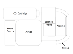
Gravicase is an Arduino controlled device which attaches to your personal electronics and, when dropped, deploys a CO2 powered airbag that engulfs and protects whatever it is attached to. The Arduino uses an accelerometer to sense when it is being dropped, as well as if it is tumbling, so that it can accurately and safely differentiate a fall compared to other movements one would take (aka walking, running, jumping, etc). This dual safety measure allows for Gravicase to avoid activating in your bag or pocket and be ready when it counts! We will detail how we accomplished this as well as more in depth measures we took for safety and execution in the "Objective" and "Designs and Solutions" sections of our wiki.
Link to GraviCase Log: here
Link to Wiki Writing Reference by Matt Rocco: here
Link to Airflow Control Tutorial by Michael Morgan: here
Link to the slides from our class presentation on Gravicase from 9.29.2017: here
Team Members
- Matt Rocco
- Michael Morgan
- Andrew O'Sullivan (TA)
Objectives
Our project objectives are as follows:
- 1) Designing a device that can fit a tablet, phone, computer, etc. while also being optimized around its component parts
- Houses the airbag in the middle so that it is centered on the device for even protection
- Trying to minimize our layout to be as discreet and form fitting as possible
- 2) Writing Arduino code which is both effective as well as safe
- Preventing our design from popping in your pocket or bag or any time other than when it is falling
- Developing durable and robust code which can handle constant data monitoring, and quickly analyze when it is being dropped from the real world information it receives
- 3) Creating an airtight system
- Preventing CO2 from escaping so that it is pressurized and ready to go when the device is dropped
- Ensuring that all of the CO2 cartridge's volume ends up in the airbag to maximize its efficiency
- Preventing CO2 from escaping so that it is pressurized and ready to go when the device is dropped
- 4) Designing an airbag which can absorb a blunt force impact as well as be easily deflated in order to be reused
- Sewing a shape that protects all parts of the device when inflated
- Finding a material that can easily be worked with as well as fits the design needs we desire (durability, as well as reusability)
- Protects all parts of the device (eg. phone screen as well as back and sides)
- Maintaining a compact and foldable form but being able to achieve the functions described above
- 5) The ability to pop the canister so that it is ready to fill the airbag upon being dropped
- Focusing on popping the canister prior to when it is necessary so that there is no inflation delay related to the CO2 canister
Challenges
- Safety
- Premature detonation of our airbag system (Literally blowing your pants off)
- Working with pressurized systems of CO2 which have the possibilities of exploding
- Cost
- Airbags are expensive and typically designed to only be used once
- CO2 canisters are going to be needed in large quantities for testing (this will inflate our actual cost)
- Power
- We need to power both an Arduino as well as a 12V solenoid valve, this requires an external power supply which will be part of our device
- It may even be necessary to have two power sources
- We need to power both an Arduino as well as a 12V solenoid valve, this requires an external power supply which will be part of our device
- Size
- Creating a device small enough to maintain the shape and convenience of your device without compromising safety or efficacy
- Working with sizing and space constraints of our parts and fitting them together in the most efficient way possible
- Airbag
- Building an airbag which will deploy in such a way as to maximize protection but still deploy in time with no snags.
- Able to absorb a blunt force impact
- Easily deflatable for reuse
- Arduino
- Code which effectively filters information in order to accurate determine if it is falling
- CO2 Canister
- Reliably popping canisters without allowing any leakage
- Keeping CO2 canister contained and integrated with the system as a whole
Costs
Hardware and Circuit
- Arduino Uno (Provided by TA)
- Arduino Accelerometer (GY-521) ~ Provided, link
- STP36NF06L Transistor ~ Provided, link with link to data sheet
Valve and Tubing
- Threaded 3/8" 24 threads / inch, 16g CO2 Cartridges ~ $47.95 for 50, link
- McMaster-Carr tube ~ $15.20, link
- CO2 (3/8") to Regulator (1/4") Converter (Lafed by our TA)
- Kobalt Mini Pressure Regulator (1/4") ~ $22.48, link Purchased at Lowe's
- Regulator(1/4") to Valve (1/4") Attachment ~ $2.39, link Purchased at Lowe's
- Electronic (1/4") Solenoid Valve ~ $12, link
- Valve (1/4") to Hose Attachment (1/4") ~ $3.12, link
- Pneumatic Tubing (1/4" ID) ~ $7.31, link
Airbag Material
- Tyvek Cloth ~ $7.35, link
- Teflon Tape (Provided by instructor)
Total Cost ~ $117.69
Estimated Unit Cost ~ $46.54
- Estimated Unit Cost is determined by scaling our cost based upon mass production. In several cases, we had to buy bulk amounts of materials but ultimately only used a small percentage of it. The estimated unit cost accounts for this and represents the cost to make multiple Gravicases.
- Example: we spent $7.31 to get 10 feet of pneumatic tubing but ultimately used less than half of a foot of it. Therefore we would be able to build 19 more Gravicases without having to spend any additional money on pneumatic tubing.
- This was the case for the Tyvek material (1/10), pneumatic tubing (1/20), CO2 canisters (most of their use was in testing causing a big spike in our total cost), and the McMaster-Carr tube (1/25).
- Values are ratios of the amount used compared to the total bought
Gantt Chart
Design Solutions:
CO2 to Airbag Design
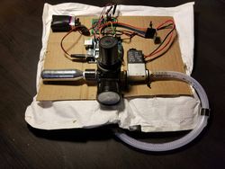
In order to get our device started, we need to be able to reliably puncture CO2 canisters. With the help of our TA, we decided to custom make a part which would allow us to simultaneously screw in and pop a CO2 canister (schematic with measurements and 3D model shown below).
It also serves the secondary purpose of being an adapter for the 3/8" male of the CO2 canisters to the 1/4" female regulator. In order to break the seal of the canister, we designed the part so that it could hold a small, hollow metal pipe (accomplished by having a small bevel in the part on which the tube rests) that would serve as a "needle" to punch through the thin perforated metal covering the opening of the CO2 container. We threaded the female side of our part (connecting to the CO2) so that it would securely hold the canister while also allowing us to screw in our CO2 and use torque to our advantage. The male side of the part is connected to a pressure regulator, which steps down the pressure coming out of the CO2 canister from approximately 800-900 PSI to a much more manageable 150 PSI (we set this value using the regulator).
We then connected the regulator to our solenoid valve through another adapter, this time a 1/4" male to 1/4" male. The solenoid valve is a 12V DC normally closed valve rated for 150 PSI which is hooked up to a circuit controlled by the Arduino. The valve is normally closed, this prevents the air from the CO2 canister from escaping. However, when voltage runs through the valve it opens, allowing air to flow and thus fill the airbag. The valve is where the electronic and mechanical components of our project meet, more of this will be discussed in the next section. On the other end of our valve was the 1/4" hose nozzle adapter which we used to secure the pneumatic tubing. Lastly, attached to the end of our tubing is the airbag, secured with an O-ring washer system so that it directs the air solely into the airbag. In order to ensure that our path from canister to airbag was airtight, we used Teflon tape to seal all of the threaded components of our system, including each individual CO2 canister (before screwing it in) to ensure maximum efficiency.
Circuit Design
In order to control the solenoid valve we designed a circuit which regulates when the valve receives voltage. The valve is normally closed, therefore as long as it has no voltage running through, no air will flow and the airbag will remain deflated. We chose a normally closed valve because it is less of a power drain when we only need it to be open for short periods of time. Additionally, a normally closed valve is more conducive to our design.
- Important Note: Make sure that your valve is pressure rated high enough for whatever you are trying to contain (in our case we needed our valve to be pressure rated for 800-900 PSI). Our valve was not rated highly enough, therefore, we required a pressure regulator in order to step down the pressure so that the air would not just overpower our normally closed valve. The large size and weight of our regulator restricted us from creating a more compact and sleek design. Because of it, we had no need to try and minimize the size of our other components due to the limiting factor of the regulator's (and the CO2 canister's) size.
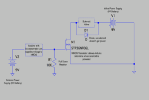
The way that we directed the voltage running through our solenoid valve was with an N-channel MOSFET (link to datasheet) controlled circuit (schematic is shown to the right). The MOSFET gate pin is hooked up to a pull down resistor and the output of Arduino digital pin 2. When the pin outputs a voltage of HIGH (5V), then the MOSFET opens allowing current and voltage to go across the valve, thus opening it. The source of the FET is connected to the solenoid valve in parallel with a diode (reverse biased when the MOSFET is closed), which helps to prevent the valve from opening independent of whether the MOSFET is closed or not. These two components are in series with a power supply (in our case a 9V battery), which is then grounded. The drain of the FET is attached to ground as well. We soldered this circuit as shown in our schematic in order to make it more durable as well as more compact.
- Note: when working with FET's it is important to ensure that you do not burn them out. Especially when trying to experiment while figuring out your circuit, a few seconds of high current can fry a MOSFET. It is also quite difficult to tell if they are burnt out or not. We ended up wasting a significant amount of time over not realizing our FET was fried. It was only after we switched to a new one that we realized the first one we had was broken and root cause of our circuit issues.
Arduino Design
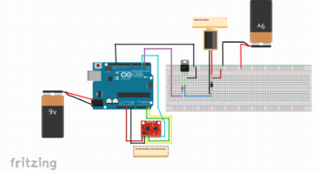
The Arduino is the means by which our device interprets whether or not it is falling. It also controls the signal input to our valve-controlling circuit. In order to process all of this, we use an accelerometer and gyroscope link to data sheet to collect data for our Arduino to interpret. We then filter this data, convert it from raw values to more manageable units, and then use these values to determine whether or not our device is dropping. In order to protect the users of Gravicase, we use a twofold system. Not only does the Arduino need to sense that it is falling fast enough (accelerometer), but it also needs to be tumbling a small but significant degree (gyroscope). We believe that this will help to avoid Gravicase going off in non-relevant situations such as in one's pocket or bag (link to source code). When the Arduino senses this drop, it sets digital pin 2 to HIGH, which then provides enough voltage to open the MOSFET and allow the solenoid valve to open. A schematic of the full system (i.e. Arduino, Accelerometer, Valve, MOSFET as well as their power supplies) is shown below.
Airbag Design
Our goal with the airbag was to create something durable, yet reusable. After some suggestions from Professor Feher and our TA Andrew, we settled on a material called Tyvek. Typically it is used to help insulate houses, but in our case we decided to uses this tough yet semi-porous material to construct airbags with our desired design needs. The other design goal of ours was to have an airbag which could be folded up compactly, yet deploy in such a way that it would envelop the entire device it was protecting (with a special emphasis on the front where it could protect the screen of a phone).
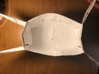
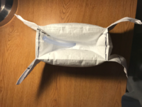
We accomplished this goal by sewing the Tyvek first into a "pillow" (we folded over and double sewed our seams in order to make it extra airtight) and then sewing in the center of the airbag (shown below). By stitching it in the middle to itself at specific points, we were able to get it to inflate into the shape that we desired. We also partially hemmed the base of the airbag so that less air would flow into the back (where the case for Gravicase would be) allowing more air to fill the sides for increased protection. Because of the material nature of Tyvek, it is extremely easy to deliberately deflate after filling it, yet it is able to easily take an impulse force while still preserving its shape and tension. An example of this is shown in the video below.
Results and Next Steps:
Unfortunately, our project faced a major issue the night before the demo. As we were fine-tuning our pressure regulator after creating a perfectly airtight system, we caused a high enough pressure build-up so that while unscrewing what we thought was a depressurized CO2 canister, our project "blew up." The CO2 canister had built up so much pressure due to the airtightness of our system that it shot itself out of our custom made part, putting a dent in the wall on its way out. Unfortunately for us, in flight, it completely stripped the threading of our CO2 to pressure regulator part, meaning we could no longer pop CO2 canisters or keep them contained in our device.
Ultimately, this meant that we were unable to demo the full extent of our project. Instead, we were limited to a funny story and showing people the click that the valve made when the accelerometer was moved quickly enough. However, even with this last minute defeat, we are both extremely happy with the outcome of our project. We were able to create a fully airtight system (to a fault), code that triggers when it is dropped and does not trigger when other everyday events are happening, and an airbag that when deployed, wraps around the device it is supposed to protect (in a short amount of time as well). The main goal we were not able to accomplish was reducing size. However, our main focus for the project was building a proof of concept of our idea, so this is something that we are alright with. As we mentioned in the section above, the regulator, along with the size of generic CO2 canisters, were limiting factors for size reduction. We would not be able to downsize very much because those two components contributed a large percent of the overall vollume of our device. If we had worked on our valve sooner instead of focusing on the airbag and code early on in the project, then we would have been able to exchange the solenoid valve we used (rated for 150 PSI) for a higher rated (yet more expensive) valve that would not have needed a pressure regulator. This would have made it much easier for us to accomplish our size-reducing goal. Additionally, in a commercial setting, we would be able to use less cumbersome CO2 canisters, so the length of the canisters would not be such a impactful limiting factor either. With both the CO2 canisters and regulator accounted for, we would be able to downsize our project to a much more convenient size that could easily fit on a smart phone or tablet. Additionally, we would be able to custom build a power supply, so we would not be stuck with two 9V batteries powering the valve and Arduino respectively.
Biggest Obstacles
- Our biggest obstacle while working on this project was our lack of adaptability. We were too rigid in our approach to our project. We became fixated on the original order of events and tried to go about our project in series rather than in parallel. Due to our lack of flexibility, we stuck to our original plan even when it did not make sense. Because of this, we encountered our valve pressure rating problem late in our project, turning something that would have been an easy fix (buying a better valve) into a huge problem. This forced us into the convoluted method of using a pressure regulator, which massively increased the weight and size of our project.
- Another obstacle we ran into was our own stubbornness. We tried to figure things out on our own for long periods of time, when other people had solved and documented the same problems we were encountering. We decided to learn from our own mistakes instead of learning from the experiences of others, which could have saved us considerable time (e.g. trying to derive our MOSFET circuit through trial and error instead of looking for similar scenarios and set ups on the internet or with classmates).
- Lastly, we had a couple of run ins with just bad luck / technical difficulties / general stupidity. We spent a few days trying to make a burnt out transistor work, we had one accelerometer give out on us, and we ran into a couple of human error problems with regard to making our custom made CO2 opener, Arduino code, and modeling software.
Future Considerations
- We believe that it would be easy to downsize our project to make it a viable commercial product.
- This could be accomplished by using a better solenoid valve rather than a pressure regulator-solenoid valve combo.
- Additionally, custom made CO2 cartridges and power supplies would allow for a more compact layout.
- Switching to a smaller Arduino board would also be a feasible strategy to bring down the overall bulkiness of our project.
- Safety
- Another way the project could improve is related to safety. The experience we had with the CO2 cartridge turned projectile is a serious safety concern, and it is something that would need to be addressed immediately if this project were to continue. We believe that some sort of pressure reliever / exhaust to be used before unscrewing a "used" CO2 canister would be a way one could increase the safety, as well as some form of harnessing the CO2 canister outside of just the threading on the adaptor (like the wire cage holding down a champagne cork).
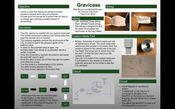
Demo Poster

