Searching for Stability Weekly Log
2/13/16
This week we successfully scaled down our initial project idea for a quadcopter to a more feasible product idea of an Arduino controlled 2-axis gimbal on a bike-mounted platform. As opposed to using an IMU, we decided to use two magnetic rotary encoders to challenge ourselves in the realm of electrical and systems engineering. Additionally, we finalized a project proposal after making some intensive revisions and created a detailed budget.
We have conducted initial research concerning the connection of the rotary magnetic encoders to the Arduino.
2/20/16
We completed a first design rendering for our stabilization platform; it is in the very early stages of development.

Components

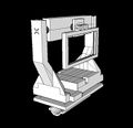
Assembled Design 1


This was the second version we designed later in the week. It illustrates how the iPhone would sit in the gimbal and where our two motors would be located.
.jpg)

We were concerned that this mounting design would be impractical for a bike-rider as the gimbal would take up the entirety of one handle. However, after some research, we found that the majority of bike mounted devices sit on the handlebar and thus plan to model a revised design after pre-existing handlebar bike mounts. Additionally, we are including more specific compartments within the back slot housing the four 9V batteries and the Arduino to eliminate unnecessary confusion and jumbling of components.
In addition to these designs, we ordered our magnetic rotary encoders and vibration dampening pads and plan to order the batteries and motors once the budget is approved.
2/27/16
Our budget was approved! We ordered two Turnigy brushless gimbal motors and four rechargeable 9V batteries. Our encoders and vibration dampening pads arrived on Wednesday, however we got two extra relay boards while the two rotary encoder shafts were omitted from the shipment. We called the vendor and the missing components were expedited to us and arrived on Saturday.
We continued to update the 3D design of our mounting platform, altering the housing of the Arduino so that it would sit under the gimbal but above the dampening pads and adding a tray for the batteries instead of a back pocket. We began test printing on Friday. We printed the two basic components that attach directly to the bike handle and tested to make sure the dimensions were correct and that they fit together snuggly. While the first print failed due to the presence of internal faces, we re-printed after fixing the file and the dimensions appeared correct when tested for fit on a bike handle. The first print of the outer support component also failed due internal faces that confused the printer. From this failed print, however, we realized that some of the proportions were off as the Arduino could not fit in its designated compartment. Thus, we altered the design to make the compartment sufficiently tall and added some structural support to the two arms of the outer frame. After printing a miniature version to ensure that there were no more internal edges, we initiated a full-sized print of the outer frame. Below are images of the mounting device with the revised frame structure, the miniature print of the outer frame, and the two basic components for direct mounting on the bike.
Updated Design

3D Print of Direct Bike Mount

Miniature Print of Outer Support


With regards to programming the Arduino, progress has been relatively slow as we both are unfamiliar with the coding language. Natalie successfully downloaded the Arduino software (IDE) to her computer and uploaded and ran the "Blink Example". We are working hard to research how to go about writing code that will receive input from the encoders regarding the position of the motors and output corrections to the motor. Additionally, we are in the process of devising test cases so that we can test our code or portions of code without having to have a fully functional mechanical model.
3/5/16
This week we printed a preliminary phone case and the attachment mechanism for the case to the gimbal. We received our two gimbal motors in the mail but have yet to plug them into anything to see what they do our what kind of output they give. We had a productive first evaluation with Deko and Professor Humberto and determined where we need to direct our focus. Figuring out how to secure wires on moving parts will be a challenge, as will be designing the control program for the Arduino. I (Natalie) need to learn how to write interrupts.
Professor Humberto also told us that he did not expect us to be able to pull off our entire goal by the end of the semester. We need to focus on being able to get any corrective motion, no matter what speed, from the gimbal.
3/26/16
After struggling to make progress with writing Arduino code and not having had time to mess around with our ordered parts, we were finally able to get into lab for a substantial period of time. We had a meeting with Deko and we were able to control a motor (fan) with an Arduino Uno and a motor shield. However, we were unable to do the same for our gimbal motors and believe we might need a motor driver in order to do so.
After some research, we determined that we probably do not need the Hall sensors that came with our magnetic rotary encoders to generate the output we want, though they might give us better data once we have everything set up correctly. Using a tutorial and a schematic we found on hobbytronics.com, we built a circuit using an Arduino Uno and a motor shield to attempt to control the encoders. The code was meant to change the brightness of an LED according to the angle of the rotary encoder. While we got the LED to light up, we ran into trouble because no matter which way we turned the encoder, the brightness value either continued to increase or, if we changed the code, continued to decrease. Therefore the position of the rotary encoder was unable to dictate brightness according to clockwise v. counter-clockwise direction... a significant problem considering the objective of our project. The circuit we used is pictured below:

While we ran out of time to continue trouble-shooting, we have set aside time in the upcoming week to continue figuring out both components: the encoders and the motors. Our to-do list is as follows:
- Research driver for our BLDC gimbal motor
- Figure out encoder code that will account for clockwise v. counter-clockwise motion
- Find detailed schematics concerning the mounting of the rotary encoder
In addition to the circuitry/coding work that we did, we also assembled the base of our gimbal mount.
