Difference between revisions of "PartyBox"
| Line 93: | Line 93: | ||
If the Arduino detects a button press, it will increase the value of the ‘counter’ variable by one. Then in the main loop of the code, we would check if counter % the number of modes == 0, 1, or 2, which corresponded to each pattern. | If the Arduino detects a button press, it will increase the value of the ‘counter’ variable by one. Then in the main loop of the code, we would check if counter % the number of modes == 0, 1, or 2, which corresponded to each pattern. | ||
| − | All of the code will be on our Github [INSERT LINK STILL], but here is | + | All of the code will be on our Github [INSERT LINK STILL], but here is a simplified version of our button code, to be generalized for any use. |
<source lang="c++"> | <source lang="c++"> | ||
#define interruptPin 2 // the pin that will be interrupted, in this case, the button pin | #define interruptPin 2 // the pin that will be interrupted, in this case, the button pin | ||
| Line 102: | Line 102: | ||
pinMode(interruptPin, INPUT_PULLUP); // declare the interrupt pin as a button | pinMode(interruptPin, INPUT_PULLUP); // declare the interrupt pin as a button | ||
attachInterrupt(digitalPinToInterrupt(interruptPin), interrupted, CHANGE); //declare how to handle the interrupt | attachInterrupt(digitalPinToInterrupt(interruptPin), interrupted, CHANGE); //declare how to handle the interrupt | ||
| + | } | ||
| + | |||
| + | void loop() { | ||
| + | if (counter % modes == 0) { // then it is mode 3 | ||
| + | Random_Dots(); // display the Random_Dots() pattern | ||
| + | } | ||
| + | else if (counter % modes == 1) { // then it is mode 1 | ||
| + | Stripes(); // display the Stripes() pattern | ||
| + | } | ||
| + | else { // it is mode 2 | ||
| + | Ring_Dots(); // display the Ring_Dots() pattern | ||
| + | } | ||
| + | FastLED.show(); | ||
| + | } | ||
} | } | ||
Revision as of 20:53, 30 April 2017
Creators: Sarah Chen, Lydia Reader, Graham Rubin, Nathan Schmetter (TA)
Contents
Overview
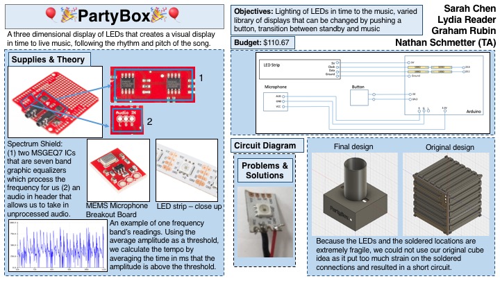
PartyBox is an easily portable three dimensional cube of LEDs that creates a visual display in time to live music, so you can have a fun party anytime or anywhere. It's the perfect size for any tabletop, approximately 4.5" in each direction. The LEDs are dynamic and change color to provide an aesthetically pleasing light show that follows along to the rhythm and pitch of the music. The pattern of the LED light show can be changed with the push of a button. A library of different patterns will be created and the user can cycle through these patterns by pushing a small button on the cube. There is an additional standby mode in which the LEDs will provide a slow gradient change of color in the absence of music.
PartyBox will be made up of 3m of an addressable RGB LED strip with a total 180 LEDs. The LEDs will be on the outside of the five surfaces of the cube (not including the bottom surface). A small microphone will be built into the box that will read the analog sound signal. A spectrum shield will be attached to an Arduino to process the sound signal. The Arduino will detect the occurrences of bass frequencies to clock the tempo of the music. The lights will be in an animated display in which the coloring of the LEDs is directed by the measured tempo and pitch. A collection of light patterns will be pre-made, and the user will be able to go to a new pattern by pressing a push button. Additionally, if the Arduino does not detect volume and rhythm for a pre-determined amount of time, it will automatically go into standby mode -- a simple, slow-changing color gradient.
Objectives
- Lighting of LEDs in time with music
- Varied library of complex visual displays rather than just flashing LEDs
- Functioning standby mode and transition between standby and music
- Ability to change the pattern of the light through the push of a button
Challenges
- Getting Arduino to discern rhythm and volume of live music.
- Creating a substantial enough library of animations to keep users' interest in the cube
- Using a push button as an input
- Avoiding overheating of LEDs and the subsequent safety hazard while being able to light all LEDs at once.
- Avoiding frying the Arduino by drawing too much power to the LEDs
- Making the Arduino able to tell the difference between background noise and music
- Learning how to use addressable LED strips
- Getting microphone to work with the spectrum shield
- Processing the data from the spectrum shield
- Making sure all LEDs are bright and have enough power
- Detecting tempo of music
Budget
| Item | Quantity | Price | Shipping | Link | Notes |
| Arduino | 1 | 0 | 0 | Provided by lab | |
| RGB LED Strip 1m | 3 | 15.95 | 9.71 | link | |
| 20 Gauge Wire | Provided by lab | ||||
| SparkFun MEMS Microphone Breakout Board | 1 | 11.95 | 0 | link | |
| Plastic Super Glue | 2 | 2.99 | 0 | link | Purchased at Dick Blick (update link) |
| Arduino push button | 1 | Included in Arduino Development Kit, provided by lab | |||
| 100 Ohm resistors | 4 | Included in Arduino Development Kit, provided by lab | |||
| Arduino Spectrum Shield | 1 | 24.95 | 2.99 | link | |
| Arduino Shield Stacking Headers | 1 | 1.95 | 0 | link | Shipped with spectrum shield |
| Power Source: Wall to barrel adapter | 1 | Provided by lab | |||
| Power Source: DC Power Source for strips | 1 | Provided by lab | |||
| Total: | $110.67 |
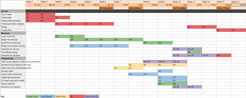
Gantt Chart
Designs & Solutions
Physical Design
With our objectives in place and an initial idea of what the we wanted the end result of PartyBox to look like, we began to design.
Our first design was an array of individual arrays. We did not even attempt this before looking into addressable LED strips for several reasons, most notably that it would take a very long time to individually wire and solder 180 (our estimate for the initial size) LEDs. In addition, for this model to work, we would have to solder each LED to a decade counter, which would add even more time and work. Furthermore, we could not design a proper model that did not block some LEDs.
For our budget, we estimated we could purchase three of the addressable LED strips, which would allow for us to have 6 stripes of 6 LEDs on each face. Because the addressable LEDs came in strips of 60 and our design called for the LEDs in bits of 6, we would need to break the strip and reconnect the LEDs with solder. This process was initially very difficult, especially because the copper connection points between LEDs was so delicate, but once we figured out a method, it was simple to repeat. The second design was a cube with stripes of LED strips running across each face. Each face would have 6 wells for each bit of 6 LEDs from the addressable strip to sit in.
The problem with the second design was that it did not leave enough room for the delicate solder between the strip and the wall of cube, so it was extremely difficult to slide the LED strip with soldered connections through the cube. As we tried to wire one face of the cube, we discovered how delicate the solder was, as it was very likely to break either itself or the copper connection. In addition to the problem of how we would get the soldered LEDs onto the cube, this design would result all of the ends of the LED strip ends to converge.
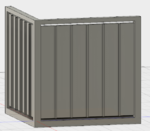
The third design expanded the dimensions of the cube so that there was a designated space for the solder, and as such, the strip could be folded on the connection wires, not on the strip joints, which is what was so fragile about the previous design. [INSERT IMAGE]
However, this design still had problems. Ultimately, it was the delicacy of the soldered LED connection joints. Though we have confidence in our solder, when moving the LED strips through the cube to place them on a face, several copper connection points became loose and broke away from their LED. Because all of the LEDs for all faces were soldered into one strip (with appropriate connection lengths) [INSERT IMAGE?], damage from one LED had an effect on all of the LEDs in connection. We discovered one broken connection when we first attempted to connect the LEDs to a face, and this one break resulted in short circuited lights. We only had one remaining working LED strip after this.
In our fourth and final design, we realized we needed to avoid soldering the LED strip at all. Therefore, we decided in a cylindrical model that could allow the LED strip to be wrapped around it continuously. This deviated from our original design of a cube, but the decision was necessary to preserve the LEDs. [INSERT IMAGE]
Controlling the LED Strips
We chose to use addressable LED strips for easy control of our lighting. The specific strips we chose are equipped with APA102 chips because we had seen excellent reviews of these strips. To control them, we used the FastLED library, which we wrote a tutorial for here. We took advantage of the color math that this library enables to be able to create patterns.
The Spectrum Shield
One of the biggest challenges in our proposed project is being able to discern the pitch of music. Pitch is physically given by the frequency of a sound wave. Since one song can have multiple pitches, there will be multiple frequencies present in the sound wave. Separating these frequencies with code would require some very complex processing, involving things such as Fourier Transforms. It would be likely that an Arduino would not be able to handle this intense of computation. To solve the issue of detecting pitch, we chose to go with the hardware solution rather than tackling the problem with code. The MSGEQ7 is a seven band graphic equalizer integrated circuit chip, which is capable of taking in a signal and splitting it into seven different frequency bands. We purchased this chip integrated onto a shield compatible with an Arduino UNO. The shield also featured inputs for an aux cable and a microphone, so that it was easy to input audio into our Arduino. We purchased the recommended microphone from the spectrum shield’s hookup guide to ensure compatibility. We also chose to use a microphone rather than an aux input to ensure that PartyBox could work with any audio source. The shield has connections for a left and right microphone, but we chose to only use a single microphone connected to the right input, and this did not noticeably affect the quality of our product.
Put something here about using the shield and link it to the tutorial that Graham is writing
Switching between Patterns: Button
We designed three patterns for the sound reactive portion of the LED. In order to switch between the three patterns, we used a button. In addition, because we wanted to prevent as much loss of data as we could, we used an interrupt to detect if the button had been pushed, so that there was not a detection algorithm that was constantly running.
We used a combination of the interrupt tutorial on this Wiki written by another project, Writing an Arduino Interrupt, as well as the interrupt tutorial from the Arduino website to understand how interrupts work. In addition to interrupt, we also used a debouncing method to prevent the Arduino from detecting multiple button presses with one button press. We found an example tutorial on Sparkfun here that we took inspiration from, as well as from the Arduino debounce tutorial here,
If the Arduino detects a button press, it will increase the value of the ‘counter’ variable by one. Then in the main loop of the code, we would check if counter % the number of modes == 0, 1, or 2, which corresponded to each pattern.
All of the code will be on our Github [INSERT LINK STILL], but here is a simplified version of our button code, to be generalized for any use.
#define interruptPin 2 // the pin that will be interrupted, in this case, the button pin
volatile int counter = 0; // volatile because this number will change with the interrupt
const int modes = 3; // the number of 'modes' or patterns we want to alternate between

void setup() {
  pinMode(interruptPin, INPUT_PULLUP); // declare the interrupt pin as a button
  attachInterrupt(digitalPinToInterrupt(interruptPin), interrupted, CHANGE); //declare how to handle the interrupt
}

void loop() {
  if (counter % modes == 0) { // then it is mode 3
   Random_Dots(); // display the Random_Dots() pattern
  }
  else if (counter % modes == 1) { // then it is mode 1
   Stripes(); // display the Stripes() pattern
  }
  else { // it is mode 2
   Ring_Dots(); // display the Ring_Dots() pattern
   }
  FastLED.show();
   }
}

void interrupted() { // if an interrupt has been detected,
  static unsigned long last_interrupt_time = 0;
  unsigned long interrupt_time = millis();
  // if the interrupt comes faster than 200 ms, assume it is a bounce and ignore
  if (interrupt_time - last_interrupt_time > 100) {
    counting();
  }
  last_interrupt_time = interrupt_time;
}

int lastButtonState = 1;
void counting() {
  int reading = digitalRead(interruptPin);
  if (reading != lastButtonState) { // if the reading at the time of the interrupt is not the same as the previous state of the button
    counter++; // let it be a button press and increment the counter variable.
  }
}
Results


