Difference between revisions of "PartyBox"
m (Protected "PartyBox" ([Edit=Allow only administrators] (indefinite) [Move=Allow only administrators] (indefinite))) |
|||
| (33 intermediate revisions by 3 users not shown) | |||
| Line 3: | Line 3: | ||
==Overview== | ==Overview== | ||
| − | PartyBox is an easily portable three dimensional cube of LEDs that creates a visual display in time to live music, so you can have a fun party anytime or anywhere. It's the perfect size for any tabletop, | + | PartyBox is an easily portable three dimensional cube of LEDs that creates a visual display in time to live music, so you can have a fun party anytime or anywhere. It's the perfect size for any tabletop, 4 inches to 5.5 inches in each direction. The LEDs are dynamic and change color to provide an aesthetically pleasing light show that follows along to the rhythm and pitch of the music. The pattern of the LED light show can be changed with the push of a button. A library of different patterns will be created and the user can cycle through these patterns by pushing a small button on the cube. There is an additional standby mode in which the LEDs will provide a slow gradient change of color in the absence of music. |
| − | PartyBox | + | |
| + | PartyBox is made up of 1m of an addressable RGB LED strip with a total 60 LEDs. The LEDs will be on the top on a cylindrical portion of the box. A small microphone will be built into the box that will read the analog sound signal. A spectrum shield will be attached to an Arduino to process the sound signal. The Arduino will detect the occurrences of bass frequencies to clock the tempo of the music. The lights will be in an animated display in which the coloring of the LEDs is directed by the measured tempo and pitch. A collection of three light patterns are pre-made, and the user will can go to a new pattern by pressing a push button. Additionally, if the Arduino does not detect volume and rhythm for a pre-determined amount of time, it will automatically go into standby mode -- a simple, slow-changing color gradient. | ||
==Objectives== | ==Objectives== | ||
| Line 30: | Line 31: | ||
|Item||Quantity||Price||Shipping||Link||Notes | |Item||Quantity||Price||Shipping||Link||Notes | ||
|- | |- | ||
| − | |Arduino||1|| | + | |Arduino||1|| || || ||Provided by lab |
|- | |- | ||
|RGB LED Strip 1m||3||15.95||9.71||[https://www.sparkfun.com/products/14015 link]|| | |RGB LED Strip 1m||3||15.95||9.71||[https://www.sparkfun.com/products/14015 link]|| | ||
|- | |- | ||
| − | |20 Gauge Wire|| || || || ||Provided by lab | + | |20 Gauge Wire||1.8m || || || ||Provided by lab |
|- | |- | ||
|SparkFun MEMS Microphone Breakout Board||1||11.95||0||[https://www.amazon.com/gp/product/B01N5OKREX/ref=oh_aui_detailpage_o03_s00?ie=UTF8&psc=1 link]|| | |SparkFun MEMS Microphone Breakout Board||1||11.95||0||[https://www.amazon.com/gp/product/B01N5OKREX/ref=oh_aui_detailpage_o03_s00?ie=UTF8&psc=1 link]|| | ||
|- | |- | ||
| − | | | + | |Krazy Glue Brush-On||2||3.79||0||[http://www.dickblick.com/items/23897-1001/ link]||Purchased at Dick Blick on Delmar loop. Website price is different than in store price |
|- | |- | ||
|Arduino push button||1|| || || ||Included in Arduino Development Kit, provided by lab | |Arduino push button||1|| || || ||Included in Arduino Development Kit, provided by lab | ||
| Line 52: | Line 53: | ||
|Power Source: DC Power Source for strips||1|| || || || Provided by lab | |Power Source: DC Power Source for strips||1|| || || || Provided by lab | ||
|- | |- | ||
| − | | || ||Total: ||$ | + | | || ||Total: ||$106.98|| || |
|} | |} | ||
| Line 64: | Line 65: | ||
===Physical Design=== | ===Physical Design=== | ||
| − | |||
====First Attempt: 3D LED Matrix==== | ====First Attempt: 3D LED Matrix==== | ||
| − | Our first design was an array of individual | + | Our first design was a small cube made up of an array of LEDs with individual LEDs suspended on the inside and outside of the cube. We did not even attempt this before looking into addressable LED strips for several reasons, most notably that it would take a very long time to individually wire and solder 180 (our estimate for the initial size) LEDs. In addition, for this model to work, we would have to solder each LED to a decade counter, which would add even more time and work. Furthermore, we could not design a proper model that did not block the visibility of some of the internal LEDs. |
====LED Strip Cube==== | ====LED Strip Cube==== | ||
| − | For our budget, we estimated we could purchase three of the addressable LED strips, which would allow for us to have 6 stripes of 6 LEDs on each face. Because the addressable LEDs came in strips of 60 and our design called for the LEDs in bits of 6, we would need to break the strip and reconnect the LEDs with solder. This process was initially very difficult, especially because the copper connection points between LEDs | + | We next looked for an easier alternative than using over a hundred individual LEDs. We decided on using addressable LED strips instead. For our budget, we estimated we could purchase three of the addressable LED strips, which would allow for us to have 6 stripes of 6 LEDs on each face. Because the addressable LEDs came in strips of 60 and our design called for the LEDs in bits of 6, we would need to break the strip and reconnect the LEDs with solder. This process was initially very difficult, especially because the copper connection points between LEDs were so delicate, but once we figured out a method to solder, it was simple to repeat. The second design was a cube that we planned to 3D print with stripes of LED strips running across each face. Each face would have 6 wells for each bit of 6 LEDs from the addressable strip to sit in. [http://www.thingiverse.com/PartyBox/about Here] is a link to our 3D files. |
[[File:second_design_combo.png|center]] | [[File:second_design_combo.png|center]] | ||
| Line 78: | Line 78: | ||
====Larger Cube==== | ====Larger Cube==== | ||
| − | The third design expanded the dimensions of the cube so that there was a designated space to support the solder joints | + | The third design expanded the dimensions of the cube so that there was a designated space to support the solder joints. This allowed the strip to be folded on the connecting wires, and not at the fragile joints. We believed that this would stabilize the joints enough so that they would not break. While learning to solder the LEDs, we broke two of the LEDs. To make the best use out of this, we used the location that those LEDs would have gone to make room for the microphone and button. |
| − | [[File: | + | [[File:Figure_2_PartyBox.PNG|center|1000px]] |
| − | Figure 2-1: As you can see in comparison with the | + | Figure 2-1: As you can see in comparison with the previous design, we expanded the length of the slots for each strip with a narrower portion on both top and bottom of the face to give length for the connections to sit and to prevent bending the soldered area through the face. We also added a defined wall for the Arduino to sit in so that it would not move. Figure 2-2: We included small holes on the top face for the microphone and button. Figure 2-3: An example of the LED strips wrapped around the cube. They are a perfect fit with the 3D printed wells, and they are not forced to be bent at the solder joint. |
| − | However, this design still had problems. | + | However, this design still had problems. |
| + | |||
| + | =====The Soldering Disaster===== | ||
| + | Our first goal of soldering was to connect all of the LEDs for one half of the cube together so that we could place them on the cube. We cut two of our three LED strips into sections of 6 LEDs. We then began to solder the sections together, with appropriate lengths of wire for their position on the cube. This was an arduous process that resulted in a lot of mistakes. One of the biggest issues was that while soldering a new section of the LEDs, the fragile copper connectors at the end of the previously connected LEDs tended to break. This resulted in a lot of back-tracking and re-soldering and ultimately, a lot of wasted time. These copper pieces were too delicate for our project as they could not handle much movement or adjustment, they simply tore. Eventually, we had 106 LEDs connected together and functioning. However, once we began to attach these LEDs to the cube, the fragile solder joints and copper pieces began to break and short circuit. At least 10 and possibly more LEDs were broken before we decided that this design was not going to work. | ||
| + | |||
| + | [[File:Good_solder_small.JPG|frame|left|A beautiful example of what the solder should look like at the end of an LED]][[File:Broken_solder_broken_dreams_small.JPG|frame|none|An example of torn of copper pieces at the end of an LED]] | ||
| + | |||
| + | <br /> | ||
====Final Design==== | ====Final Design==== | ||
| − | In our fourth and final design, we realized we needed to avoid soldering the LED strip at all. Therefore, we decided in a cylindrical model that could allow the LED strip to be wrapped around it continuously. This deviated from our original design of a cube, but the decision was necessary to preserve the LEDs. | + | In our fourth and final design, we realized we needed to avoid soldering the LED strip at all. Therefore, we decided in a cylindrical model that could allow the LED strip to be wrapped around it continuously. This deviated from our original design of a cube, but the decision was necessary to preserve the LEDs. We also now had to scale back our design from 180 LEDs to 60, because only one strip of LEDs was still fully functional. |
[[File:final_design_combo.png|center]] | [[File:final_design_combo.png|center]] | ||
| Line 99: | Line 106: | ||
===The Spectrum Shield=== | ===The Spectrum Shield=== | ||
| − | One of the biggest challenges in our proposed project is being able to discern the pitch of music. Pitch is physically given by the frequency of a sound wave. Since one song can have multiple pitches, there will be multiple frequencies present in the sound wave. Separating these frequencies with code would require some very complex processing, involving things such as Fourier Transforms. It would be likely that an Arduino would not be able to handle this intense of computation. To solve the issue of detecting pitch, we chose to go with the hardware solution rather than tackling the problem with code. The [https://www.sparkfun.com/products/10468 MSGEQ7] is a seven band graphic equalizer integrated circuit chip, which is capable of taking in a signal and splitting it into seven different frequency bands. We purchased this chip integrated onto a shield compatible with an Arduino UNO. The shield also featured inputs for an aux cable and a microphone, so that it was easy to input audio into our Arduino. We purchased the recommended microphone from the spectrum shield’s [https://learn.sparkfun.com/tutorials/spectrum-shield-hookup-guide hookup guide] to ensure compatibility. We also chose to use a microphone rather than an aux input to ensure that PartyBox could work with any audio source. The shield has connections for a left and right microphone, but we chose to only use a single microphone connected to the right input, and this did not noticeably affect the quality of our product. | + | One of the biggest challenges in our proposed project is being able to discern the pitch of music. Pitch is physically given by the frequency of a sound wave. Since one song can have multiple pitches, there will be multiple frequencies present in the sound wave. Separating these frequencies with code would require some very complex processing, involving things such as Fourier Transforms. It would be likely that an Arduino would not be able to handle this intense of computation. To solve the issue of detecting pitch, we chose to go with the hardware solution rather than tackling the problem with code. The [https://www.sparkfun.com/products/10468 MSGEQ7] is a seven band graphic equalizer integrated circuit chip, which is capable of taking in a signal and splitting it into seven different frequency bands. We purchased this chip integrated onto a shield compatible with an Arduino UNO. The shield also featured inputs for an aux cable and a microphone, so that it was easy to input audio into our Arduino. We purchased the recommended microphone from the spectrum shield’s [https://learn.sparkfun.com/tutorials/spectrum-shield-hookup-guide hookup guide] to ensure compatibility. We also chose to use a microphone rather than an aux input to ensure that PartyBox could work with any audio source. The shield has connections for a left and right microphone, but we chose to only use a single microphone connected to the right input, and this did not noticeably affect the quality of our product. For further instructions on using the spectrum shield, check out the tutorial we wrote [http://classes.engineering.wustl.edu/ese205/Using_the_Sparkfun_Spectrum_Shield here]. |
| − | + | ===Detecting Music=== | |
| + | To eliminate lighting of LEDs when music is not playing, we opted to give PartyBox the ability to detect whether music is playing rather than a second mode switching button. Detecting if music is playing with the Arduino functions much like a de-bounced button. The Arduino calculates numerous values, namely the average amplitude of bands one, three, four, and five, as well as the average of the max amplitude values measured by the microphone. A function named “isMusicOn” compares these values to several predetermine amplitude thresholds. If it passes the first comparison, it must wait a few milliseconds and check again; if both comparisons pass, the function returns a “true” value. | ||
| + | |||
| + | This function is utilized twice in a cycle of our code. It’s called in the loop, a call that delta times itself and the later call. It is later called in the finite state machine, where if enough time has passed since its last call it will compare the earlier value to the current one. If either are true, then it declares that music is on, while both need to be false for it to determine that music is not playing. This prevents PartyBox from detecting no music when there’s a dip in volume in a song for less than five seconds, however it allows PartyBox to more easily detect music where there is just loud, nearby ambient noise. To counteract this, I raised the number of utilized bands in “isMusicOn” from just the one bass band to the current five employed values. | ||
| + | [[File:IsMusicOn.png||550px||thumb||center||This is the isMusicOn function used by the Arduino to detect is music is playing]] | ||
| + | |||
| + | ===Calculating Tempo=== | ||
| + | Calculating tempo became significantly more feasible once the Spectrum Shield and microphone were attached to our Arduino. To calculate tempo, we choose to look specifically at the bass frequency band because of its association with most common rhythm instruments (bass and drums). The first step the Arduino takes is to simultaneously gather sufficient data points (amplitude and their times taken) and determine the average amplitude of the bass band; this is performed by the function “determineAmpRange,” and consequently reduces the amount of audio data loss to below 5%. | ||
| + | |||
| + | The next step is to determine if a note is being played, and if it is, measure its length in milliseconds. If the measured bass amplitude starts below, rises above, and then is once again below the average bass amplitude, then a beat was played. The Arduino uses the previously measured times taken associated with the measured amplitudes to calculate a beat’s length. | ||
| + | |||
| + | These beat length values are added to a linked list and then averaged. This averaged value is in units of milliseconds per beat, thus it is a simple unit conversion to beats per minute, the unit of tempo. These tempo values are added to a second linked list and averaged to avoid rapid changes in lighting pacing. Once calculated, the tempo is converted back into units of milliseconds per beat to be used for pacing the LED lighting. | ||
| + | |||
| + | ===Lighting Patterns=== | ||
| + | One important challenge of our project was creating lighting patterns that were visibly following the music. We decided that in general, the color of the LEDs would be determined by the pitch of the music and the speed of the pattern would be controlled by the tempo of the music. For the cube design, some complicated lighting patterns were in the works. However, when the physical design of the cube changed at the end of the semester, the lighting patterns had to be simplified so that there was enough time to complete them before the demo. Ultimately, three music responsive patterns were created. | ||
| + | |||
| + | These patterns all responded every quarter beat, because we found that this was the frequency fast enough for it to be clear that the light was responding to sound, but slow enough that the program had time to calculate tempo and take measurements. A quarter beat was chosen because in music, factors of two correspond to different note lengths and it is more likely that the pattern will hit more notes if it is updated every quarter beat than say, every fifth of a beat. | ||
| + | |||
| + | The first pattern consisted of randomized dots of light. Every quarter beat, semi-random LEDs were lit on the cylinder with colors that corresponded to the pitch of the music. The number of LEDs of each color depended on how loud that note was in relation to the other notes of the song. The position of the LEDs on the cylinder in general also corresponded with pitch, with higher frequencies toward the top of the cylinder and lower frequencies toward the bottom. | ||
| + | |||
| + | The second pattern had two components. The bottom stripe of the cylinder changed colors to the most prominent note every quarter beat. Every beat, all of the stripes on the cylinder moved up one position. This pattern was designed to more easily show off the work we had done with tempo detection, since it had a component that kept the beat of the music. | ||
| + | |||
| + | The final pattern we chose only featured the top six frequency bands. This is because the lowest frequency band is so uncommon in music, that it almost never surpassed in volume the other frequency bands. Each of the six horizontal stripes on the cylinder corresponded with the six remaining frequency bands. When the frequency band surpassed a certain threshold, which was different for most bands, the corresponding stripe on the cylinder lit up. The threshold was determined by using the average amplitude for all seven frequency bands plus a different constant for each frequency. The constants were different because some bands tended to give higher values than others, for similar perceived volumes. For example, band 4 often gave very high amplitudes. The main reason for this is because in a loud room, this is the frequency range that most of the ambient noise is detected in by the microphone. The pattern was also updated every quarter beat. | ||
| + | |||
| + | For all of these patterns we used delta-timing to update the lights, this way as much time as possible could be spent collecting and processing the audio data. It only took 1 to 2 ms for each pattern to run, and then once it ran once, the LEDs would stay lit until the pattern was updated. | ||
===Switching between Patterns: Button === | ===Switching between Patterns: Button === | ||
| Line 110: | Line 141: | ||
If the Arduino detects a button press, it will increase the value of the ‘counter’ variable by one. Then in the main loop of the code, we would check if counter % the number of modes == 0, 1, or 2, which corresponded to each pattern. | If the Arduino detects a button press, it will increase the value of the ‘counter’ variable by one. Then in the main loop of the code, we would check if counter % the number of modes == 0, 1, or 2, which corresponded to each pattern. | ||
| − | All of the code will be on our | + | All of the code will be on our [https://bitbucket.org/grahamkrubin/partybox/ BitBucket], but here is a simplified version of our button code, to be generalized for any use. |
<source lang="c++"> | <source lang="c++"> | ||
#define interruptPin 2 // the pin that will be interrupted, in this case, the button pin | #define interruptPin 2 // the pin that will be interrupted, in this case, the button pin | ||
| Line 156: | Line 187: | ||
==Results== | ==Results== | ||
===Final Product=== | ===Final Product=== | ||
| − | [[File:PartyBox_Final.MOV]] | + | [[File:PartyBox_Final_Design_Medium.JPG|frame|The front face of the final PartyBox design|400px|left]] |
| − | + | [[File:PartyBox_Final.MOV|center|frame|The PartyBox in action]] | |
| + | |||
| + | <center> | ||
| + | <gallery> | ||
| + | File:Microphone_hole.JPG|A small hole on the top of PartyBox for the microphone | ||
| + | File:LED_hole.JPG|A hole on the top of PartyBox for the LED wires to feed through to connect to the Arduino | ||
| + | File:Power_hole.jpg|A small opening on the back of PartyBox for the wiring for power to run through | ||
| + | </gallery> | ||
| + | </center> | ||
| + | |||
| − | Take note in the video | + | Here we have the final version of the PartyBox. Take note in the video the display of the standby pattern before music begins playing and after it stops. |
===Comparison to Objectives=== | ===Comparison to Objectives=== | ||
| − | Our final product largely fulfilled all of our objectives, though it did have some shortcomings. For example, physical percussion on PartyBox near the position of the microphone could trick it into thinking that music was playing when it was not. However, it was mostly accurate during normal use in which no one was actually tapping it. During some songs with prolonged quiet sections, it would switch out of music mode, but it would switch back in when the song picked back up. Also, though a large majority of the time it was able to tell when music was not playing, there were a few people, such as Nathan, who had voices that were able to trick it into thinking music was playing more often than others. This is because their voices were relatively loud and within the frequency bands that we used to decide music was playing. For our other objectives, we were successful in creating three patterns that were able to be changed by pressing the button. The lighting also did clearly respond to the music. | + | Our final product largely fulfilled all of our objectives, though it did have some shortcomings. For example, physical percussion on PartyBox near the position of the microphone could trick it into thinking that music was playing when it was not. However, it was mostly accurate during normal use in which no one was actually tapping it. During some songs with prolonged quiet sections, it would switch out of music mode, but it would switch back in when the song picked back up. Also, though a large majority of the time it was able to tell when music was not playing, there were a few people, such as Nathan, who had voices that were able to trick it into thinking music was playing more often than others. This is because their voices were relatively loud and within the frequency bands that we used to decide music was playing. For our other objectives, we were successful in creating three patterns that were able to be changed by pressing the button. The lighting also did clearly respond to the music. The tempo our code calculated was typically within 5% of the actual tempo of the song. |
===How it could have Gone Better=== | ===How it could have Gone Better=== | ||
| Line 168: | Line 208: | ||
== Presentation Poster == | == Presentation Poster == | ||
| − | [[File: | + | [[File: Partyboxposterupdated.jpg|720px]] |
==Important Links == | ==Important Links == | ||
===3D Printer Designs === | ===3D Printer Designs === | ||
| + | [http://www.thingiverse.com/PartyBox/about Thingiverse] | ||
| − | === | + | ===BitBucket Code === |
| + | [https://bitbucket.org/grahamkrubin/partybox/ BitBucket] | ||
===Tutorials=== | ===Tutorials=== | ||
[[Using Arduino FastLED Library| HowTo: Use the FastLED Library]] | [[Using Arduino FastLED Library| HowTo: Use the FastLED Library]] | ||
| + | |||
| + | [[Using the Sparkfun Spectrum Shield| HowTo: Use the Spectrum Shield]] | ||
[[Category:Projects]] | [[Category:Projects]] | ||
[[Category:Spring 2017 Projects]] | [[Category:Spring 2017 Projects]] | ||
Latest revision as of 16:08, 3 May 2017
Creators: Sarah Chen, Lydia Reader, Graham Rubin, Nathan Schmetter (TA)
Contents
- 1 Overview
- 2 Objectives
- 3 Challenges
- 4 Budget
- 5 Gantt Chart
- 6 Designs & Solutions
- 7 Results
- 8 Presentation Poster
- 9 Important Links
Overview
PartyBox is an easily portable three dimensional cube of LEDs that creates a visual display in time to live music, so you can have a fun party anytime or anywhere. It's the perfect size for any tabletop, 4 inches to 5.5 inches in each direction. The LEDs are dynamic and change color to provide an aesthetically pleasing light show that follows along to the rhythm and pitch of the music. The pattern of the LED light show can be changed with the push of a button. A library of different patterns will be created and the user can cycle through these patterns by pushing a small button on the cube. There is an additional standby mode in which the LEDs will provide a slow gradient change of color in the absence of music.
PartyBox is made up of 1m of an addressable RGB LED strip with a total 60 LEDs. The LEDs will be on the top on a cylindrical portion of the box. A small microphone will be built into the box that will read the analog sound signal. A spectrum shield will be attached to an Arduino to process the sound signal. The Arduino will detect the occurrences of bass frequencies to clock the tempo of the music. The lights will be in an animated display in which the coloring of the LEDs is directed by the measured tempo and pitch. A collection of three light patterns are pre-made, and the user will can go to a new pattern by pressing a push button. Additionally, if the Arduino does not detect volume and rhythm for a pre-determined amount of time, it will automatically go into standby mode -- a simple, slow-changing color gradient.
Objectives
- Lighting of LEDs in time with music
- Varied library of complex visual displays rather than just flashing LEDs
- Functioning standby mode and transition between standby and music
- Ability to change the pattern of the light through the push of a button
Challenges
- Getting Arduino to discern rhythm and volume of live music.
- Creating a substantial enough library of animations to keep users' interest in the cube
- Using a push button as an input
- Avoiding overheating of LEDs and the subsequent safety hazard while being able to light all LEDs at once.
- Avoiding frying the Arduino by drawing too much power to the LEDs
- Making the Arduino able to tell the difference between background noise and music
- Learning how to use addressable LED strips
- Getting microphone to work with the spectrum shield
- Processing the data from the spectrum shield
- Making sure all LEDs are bright and have enough power
- Detecting tempo of music
Budget
| Item | Quantity | Price | Shipping | Link | Notes |
| Arduino | 1 | Provided by lab | |||
| RGB LED Strip 1m | 3 | 15.95 | 9.71 | link | |
| 20 Gauge Wire | 1.8m | Provided by lab | |||
| SparkFun MEMS Microphone Breakout Board | 1 | 11.95 | 0 | link | |
| Krazy Glue Brush-On | 2 | 3.79 | 0 | link | Purchased at Dick Blick on Delmar loop. Website price is different than in store price |
| Arduino push button | 1 | Included in Arduino Development Kit, provided by lab | |||
| 100 Ohm resistors | 4 | Included in Arduino Development Kit, provided by lab | |||
| Arduino Spectrum Shield | 1 | 24.95 | 2.99 | link | |
| Arduino Shield Stacking Headers | 1 | 1.95 | 0 | link | Shipped with spectrum shield |
| Power Source: Wall to barrel adapter | 1 | Provided by lab | |||
| Power Source: DC Power Source for strips | 1 | Provided by lab | |||
| Total: | $106.98 |
Gantt Chart

Designs & Solutions
Physical Design
First Attempt: 3D LED Matrix
Our first design was a small cube made up of an array of LEDs with individual LEDs suspended on the inside and outside of the cube. We did not even attempt this before looking into addressable LED strips for several reasons, most notably that it would take a very long time to individually wire and solder 180 (our estimate for the initial size) LEDs. In addition, for this model to work, we would have to solder each LED to a decade counter, which would add even more time and work. Furthermore, we could not design a proper model that did not block the visibility of some of the internal LEDs.
LED Strip Cube
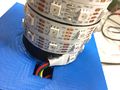
We next looked for an easier alternative than using over a hundred individual LEDs. We decided on using addressable LED strips instead. For our budget, we estimated we could purchase three of the addressable LED strips, which would allow for us to have 6 stripes of 6 LEDs on each face. Because the addressable LEDs came in strips of 60 and our design called for the LEDs in bits of 6, we would need to break the strip and reconnect the LEDs with solder. This process was initially very difficult, especially because the copper connection points between LEDs were so delicate, but once we figured out a method to solder, it was simple to repeat. The second design was a cube that we planned to 3D print with stripes of LED strips running across each face. Each face would have 6 wells for each bit of 6 LEDs from the addressable strip to sit in. Here is a link to our 3D files.

From Fig. 1-1, you can see the the slots for the strips of the LED strip to sit in. From Fig. 1-2, we would have the wires that connected the strips slide in through the slit at the top of each face.
The problem with the second design was that it did not leave enough room for the delicate solder joints between the strip and the wall of cube, so it was extremely difficult to slide the LED strip with soldered connections through the cube. Also it would require bending the strips at the solder joints, which was basically impossible without damaging the strip. As we tried to wire one face of the cube, we discovered how delicate the solder was, as it was very likely to break either itself or the copper connection.
Larger Cube
The third design expanded the dimensions of the cube so that there was a designated space to support the solder joints. This allowed the strip to be folded on the connecting wires, and not at the fragile joints. We believed that this would stabilize the joints enough so that they would not break. While learning to solder the LEDs, we broke two of the LEDs. To make the best use out of this, we used the location that those LEDs would have gone to make room for the microphone and button.

Figure 2-1: As you can see in comparison with the previous design, we expanded the length of the slots for each strip with a narrower portion on both top and bottom of the face to give length for the connections to sit and to prevent bending the soldered area through the face. We also added a defined wall for the Arduino to sit in so that it would not move. Figure 2-2: We included small holes on the top face for the microphone and button. Figure 2-3: An example of the LED strips wrapped around the cube. They are a perfect fit with the 3D printed wells, and they are not forced to be bent at the solder joint.
However, this design still had problems.
The Soldering Disaster
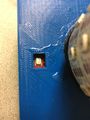
Our first goal of soldering was to connect all of the LEDs for one half of the cube together so that we could place them on the cube. We cut two of our three LED strips into sections of 6 LEDs. We then began to solder the sections together, with appropriate lengths of wire for their position on the cube. This was an arduous process that resulted in a lot of mistakes. One of the biggest issues was that while soldering a new section of the LEDs, the fragile copper connectors at the end of the previously connected LEDs tended to break. This resulted in a lot of back-tracking and re-soldering and ultimately, a lot of wasted time. These copper pieces were too delicate for our project as they could not handle much movement or adjustment, they simply tore. Eventually, we had 106 LEDs connected together and functioning. However, once we began to attach these LEDs to the cube, the fragile solder joints and copper pieces began to break and short circuit. At least 10 and possibly more LEDs were broken before we decided that this design was not going to work.


Final Design
In our fourth and final design, we realized we needed to avoid soldering the LED strip at all. Therefore, we decided in a cylindrical model that could allow the LED strip to be wrapped around it continuously. This deviated from our original design of a cube, but the decision was necessary to preserve the LEDs. We also now had to scale back our design from 180 LEDs to 60, because only one strip of LEDs was still fully functional.

Figure 3-1: The final design of our PartyBox. The LEDs wrap around the cylinder and the Arduino and other physical components will be stored inside the box embossed with the PartyBox label. Figure 3-2: This is the diffuser that goes over the LEDs on the cylinder. However, we did not get to print this because of the time constraints. Figure 3-3: The bottom plate of the box. This includes a defined spot for the Arduino. However, we did not get to print this either due to time constraints.
Controlling the LED Strips
We chose to use addressable LED strips for easy control of our lighting. The specific strips we chose are equipped with APA102 chips because we had seen excellent reviews of these strips. To control them, we used the FastLED library, which we wrote a tutorial for here. We took advantage of the color math that this library enables to be able to create patterns.
Powering the LED Strips
One challenge we faced was powering the strips without destroying our Arduino. The Arduino could not provide enough power to the strips without overheating, so an external power supply was used instead. It was important also to make sure that the power supply did not give too much current and break the strip. To do this, we tested the power source to determine the maximum current value our strips needed to run our code. The voltage was set to 5V and the current was set initially to a very small amount, 100 mA. The strip was wired to this source, and it was seen that 100 mA was not enough current for the strip to behave normally. The current was then set to increasingly higher amounts in increments of 100 mA, until it was enough to power the strip. It was found that with our code, 1.0 A at 5V was enough power for the strips to behave normally. During the demo, we set the power supply to these values and wired the ground and +5V wires to this power supply through an external breadboard.
The Spectrum Shield
One of the biggest challenges in our proposed project is being able to discern the pitch of music. Pitch is physically given by the frequency of a sound wave. Since one song can have multiple pitches, there will be multiple frequencies present in the sound wave. Separating these frequencies with code would require some very complex processing, involving things such as Fourier Transforms. It would be likely that an Arduino would not be able to handle this intense of computation. To solve the issue of detecting pitch, we chose to go with the hardware solution rather than tackling the problem with code. The MSGEQ7 is a seven band graphic equalizer integrated circuit chip, which is capable of taking in a signal and splitting it into seven different frequency bands. We purchased this chip integrated onto a shield compatible with an Arduino UNO. The shield also featured inputs for an aux cable and a microphone, so that it was easy to input audio into our Arduino. We purchased the recommended microphone from the spectrum shield’s hookup guide to ensure compatibility. We also chose to use a microphone rather than an aux input to ensure that PartyBox could work with any audio source. The shield has connections for a left and right microphone, but we chose to only use a single microphone connected to the right input, and this did not noticeably affect the quality of our product. For further instructions on using the spectrum shield, check out the tutorial we wrote here.
Detecting Music
To eliminate lighting of LEDs when music is not playing, we opted to give PartyBox the ability to detect whether music is playing rather than a second mode switching button. Detecting if music is playing with the Arduino functions much like a de-bounced button. The Arduino calculates numerous values, namely the average amplitude of bands one, three, four, and five, as well as the average of the max amplitude values measured by the microphone. A function named “isMusicOn” compares these values to several predetermine amplitude thresholds. If it passes the first comparison, it must wait a few milliseconds and check again; if both comparisons pass, the function returns a “true” value.
This function is utilized twice in a cycle of our code. It’s called in the loop, a call that delta times itself and the later call. It is later called in the finite state machine, where if enough time has passed since its last call it will compare the earlier value to the current one. If either are true, then it declares that music is on, while both need to be false for it to determine that music is not playing. This prevents PartyBox from detecting no music when there’s a dip in volume in a song for less than five seconds, however it allows PartyBox to more easily detect music where there is just loud, nearby ambient noise. To counteract this, I raised the number of utilized bands in “isMusicOn” from just the one bass band to the current five employed values.

Calculating Tempo
Calculating tempo became significantly more feasible once the Spectrum Shield and microphone were attached to our Arduino. To calculate tempo, we choose to look specifically at the bass frequency band because of its association with most common rhythm instruments (bass and drums). The first step the Arduino takes is to simultaneously gather sufficient data points (amplitude and their times taken) and determine the average amplitude of the bass band; this is performed by the function “determineAmpRange,” and consequently reduces the amount of audio data loss to below 5%.
The next step is to determine if a note is being played, and if it is, measure its length in milliseconds. If the measured bass amplitude starts below, rises above, and then is once again below the average bass amplitude, then a beat was played. The Arduino uses the previously measured times taken associated with the measured amplitudes to calculate a beat’s length.
These beat length values are added to a linked list and then averaged. This averaged value is in units of milliseconds per beat, thus it is a simple unit conversion to beats per minute, the unit of tempo. These tempo values are added to a second linked list and averaged to avoid rapid changes in lighting pacing. Once calculated, the tempo is converted back into units of milliseconds per beat to be used for pacing the LED lighting.
Lighting Patterns
One important challenge of our project was creating lighting patterns that were visibly following the music. We decided that in general, the color of the LEDs would be determined by the pitch of the music and the speed of the pattern would be controlled by the tempo of the music. For the cube design, some complicated lighting patterns were in the works. However, when the physical design of the cube changed at the end of the semester, the lighting patterns had to be simplified so that there was enough time to complete them before the demo. Ultimately, three music responsive patterns were created.
These patterns all responded every quarter beat, because we found that this was the frequency fast enough for it to be clear that the light was responding to sound, but slow enough that the program had time to calculate tempo and take measurements. A quarter beat was chosen because in music, factors of two correspond to different note lengths and it is more likely that the pattern will hit more notes if it is updated every quarter beat than say, every fifth of a beat.
The first pattern consisted of randomized dots of light. Every quarter beat, semi-random LEDs were lit on the cylinder with colors that corresponded to the pitch of the music. The number of LEDs of each color depended on how loud that note was in relation to the other notes of the song. The position of the LEDs on the cylinder in general also corresponded with pitch, with higher frequencies toward the top of the cylinder and lower frequencies toward the bottom.
The second pattern had two components. The bottom stripe of the cylinder changed colors to the most prominent note every quarter beat. Every beat, all of the stripes on the cylinder moved up one position. This pattern was designed to more easily show off the work we had done with tempo detection, since it had a component that kept the beat of the music.
The final pattern we chose only featured the top six frequency bands. This is because the lowest frequency band is so uncommon in music, that it almost never surpassed in volume the other frequency bands. Each of the six horizontal stripes on the cylinder corresponded with the six remaining frequency bands. When the frequency band surpassed a certain threshold, which was different for most bands, the corresponding stripe on the cylinder lit up. The threshold was determined by using the average amplitude for all seven frequency bands plus a different constant for each frequency. The constants were different because some bands tended to give higher values than others, for similar perceived volumes. For example, band 4 often gave very high amplitudes. The main reason for this is because in a loud room, this is the frequency range that most of the ambient noise is detected in by the microphone. The pattern was also updated every quarter beat.
For all of these patterns we used delta-timing to update the lights, this way as much time as possible could be spent collecting and processing the audio data. It only took 1 to 2 ms for each pattern to run, and then once it ran once, the LEDs would stay lit until the pattern was updated.
Switching between Patterns: Button
We designed three patterns for the sound reactive portion of the LED. In order to switch between the three patterns, we used a button. In addition, because we wanted to prevent as much loss of data as we could, we used an interrupt to detect if the button had been pushed, so that there was not a detection algorithm that was constantly running.
We used a combination of the interrupt tutorial on this Wiki written by another project, Writing an Arduino Interrupt, as well as the interrupt tutorial from the Arduino website to understand how interrupts work. In addition to interrupt, we also used a debouncing method to prevent the Arduino from detecting multiple button presses with one button press. We found an example tutorial on Sparkfun here that we took inspiration from, as well as from the Arduino debounce tutorial here,
If the Arduino detects a button press, it will increase the value of the ‘counter’ variable by one. Then in the main loop of the code, we would check if counter % the number of modes == 0, 1, or 2, which corresponded to each pattern.
All of the code will be on our BitBucket, but here is a simplified version of our button code, to be generalized for any use.
#define interruptPin 2 // the pin that will be interrupted, in this case, the button pin
volatile int counter = 0; // volatile because this number will change with the interrupt
const int modes = 3; // the number of 'modes' or patterns we want to alternate between

void setup() {
  pinMode(interruptPin, INPUT_PULLUP); // declare the interrupt pin as a button
  attachInterrupt(digitalPinToInterrupt(interruptPin), interrupted, CHANGE); //declare how to handle the interrupt
}

void loop() {
  if (counter % modes == 0) { // then it is mode 3
   Random_Dots(); // display the Random_Dots() pattern
  }
  else if (counter % modes == 1) { // then it is mode 1
   Stripes(); // display the Stripes() pattern
  }
  else { // it is mode 2
   Ring_Dots(); // display the Ring_Dots() pattern
   }
  FastLED.show();
   }
}

void interrupted() { // if an interrupt has been detected,
  static unsigned long last_interrupt_time = 0;
  unsigned long interrupt_time = millis();
  // if the interrupt comes faster than 200 ms, assume it is a bounce and ignore
  if (interrupt_time - last_interrupt_time > 100) {
    counting();
  }
  last_interrupt_time = interrupt_time;
}

int lastButtonState = 1;
void counting() {
  int reading = digitalRead(interruptPin);
  if (reading != lastButtonState) { // if the reading at the time of the interrupt is not the same as the previous state of the button
    counter++; // let it be a button press and increment the counter variable.
  }
}
Results
Final Product

A small hole on the top of PartyBox for the microphone
A hole on the top of PartyBox for the LED wires to feed through to connect to the Arduino
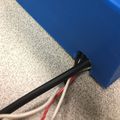
A small opening on the back of PartyBox for the wiring for power to run through


Here we have the final version of the PartyBox. Take note in the video the display of the standby pattern before music begins playing and after it stops.
Comparison to Objectives
Our final product largely fulfilled all of our objectives, though it did have some shortcomings. For example, physical percussion on PartyBox near the position of the microphone could trick it into thinking that music was playing when it was not. However, it was mostly accurate during normal use in which no one was actually tapping it. During some songs with prolonged quiet sections, it would switch out of music mode, but it would switch back in when the song picked back up. Also, though a large majority of the time it was able to tell when music was not playing, there were a few people, such as Nathan, who had voices that were able to trick it into thinking music was playing more often than others. This is because their voices were relatively loud and within the frequency bands that we used to decide music was playing. For our other objectives, we were successful in creating three patterns that were able to be changed by pressing the button. The lighting also did clearly respond to the music. The tempo our code calculated was typically within 5% of the actual tempo of the song.
How it could have Gone Better
We severely underestimated how fragile the copper connections were between LEDs on the LED strip. We knew it was possible to cut the strip and solder them together, however this was not at all practical for our purposes as any movement or adjusting of the strip tended to tear the copper pieces and create short circuits and damage LEDs. We saw how fragile these copper pieces were early on to our soldering, however we held out hope that once we had the LEDs stabilized onto our 3D model, this would no longer be a problem. We were wrong and we discovered this much too late, just a few days before the demo. It would have been a good idea to try connecting the LEDs to the cube earlier, rather than waiting until we had a lot soldered together, so that we could have given up on this design much sooner. Continuing with our plan meant that we wasted a lot of very valuable time soldering. We also should have aimed to have the 3D design completed much earlier, rather than at the end of the process. Because of these mistakes, we had to pivot and change our 3D design very late in the game. We adjusted our 3D design to be a cylinder instead of a cube to avoid soldering in the middle of the strips altogether. Since the 3D design was changed, the patterns also had to be radically adjusted to fit the new design. A lot of valuable time for debugging and improving was instead spent on changing the previously done work to fit the new design. We would have been able to make the patterns more complex and the tempo detection and music detection more accurate if we had made it a priority to finish the physical assembly earlier.
Presentation Poster
