Difference between revisions of "WarmUp Boot"
| Line 66: | Line 66: | ||
== Design + Solutions == | == Design + Solutions == | ||
| − | == How To: Create a Flashy, Blinking Turn-On Sequence for a Button with LEDs == | + | == How To: Create a Flashy, Blinking Turn-On Sequence for a Button with LEDs == |
| + | Initially, we were going to use nifty buttons with built-in LEDs to indicate that the system was on and running, but unfortunately we found that the leads for the LED part of the button were super flimsy and would turn would break easily upon soldering. So we had to think creatively to come up with another to indicate to the user that the system was turned on in the interface, so we turned our attention to the row of LEDs already being used to indicate the heat level of the pads. With quite a bit of ease, we were able to have them blink in fun sequence in response to the button being pressed. Now, allow us to teach you how to do the same! | ||
| + | |||
| + | Materials: Arduino Mega board, Tactile pushbutton (easily found on Sparkfun), one 10kΩ resistor, four 220Ω resistors, 4 LEDs, wires | ||
| + | |||
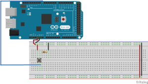
| + | Step 1: Connect the button. This we took directly from Arduino’s tutorial, which can be found [https://www.arduino.cc/en/tutorial/button here] (the resistor seen is a 10kohm resistor). The placement of the button pin is up to you, as long as it is connected to a digital pin. | ||
| + | [[File:How to- connect button.png|thumb|Circuit diagram for button alone]] | ||
| + | |||
| + | Step 2: Now time for the coding! It is a very simple bit of code, which is can be found [https://github.com/asalama97/WarmUp-Boot/blob/master/Button_Test.ino here]. Read through the comments to get a full understanding of it, and make sure that the declaration of buttonPin matches the digital pin on the Arduino that your button is connected to. | ||
| + | |||
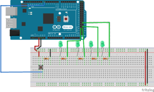
| + | Step 3: Now that the button is connected to the board, it is time to add our LED lights, along with their resistors. For our project, we used 4, as seen in the circuit diagram. | ||
| + | [[File:How_to-_blinking_leds.png|thumbnail|Circuit diagram for button + LEDs]] | ||
| + | |||
| + | Make sure that at the end of each LED resistor, a wire runs from a pin parallel to the resistor lead and into a digital pin on the Arduino Mega. | ||
| + | |||
| + | Step 4: More code! You can find it [https://github.com/asalama97/WarmUp-Boot/blob/master/button_turn_on.ino here], but we are really just building off the original button code, only with a couple additions: | ||
| + | *Initialization of the LEDs onto the Arduino (same as for the button) | ||
| + | *Declaring the LEDs as “Outputs” in the void setup (as the button is declared as an Input) | ||
| + | *Including a for loop inside the if statement portion in which the button and system are turned on. | ||
| + | **Once the for loop conditions are set, the blinking sequence is really up to you. Just write “digitalWrite(led_, HIGH) to turn the LED of your choice on, and add a very small delay in between the next course of action | ||
| + | **Also make sure to include “digitalWrite(led_, LOW)” for each LED under the else if condition where the system is off, just to ensure that every light is off when the system is off | ||
| + | |||
| + | And that’s it - go blink away! | ||
== How To: Control a Series of LEDs with a Potentiometer == | == How To: Control a Series of LEDs with a Potentiometer == | ||
Revision as of 07:23, 2 May 2017
Contents
- 1 Team Members
- 2 Overview
- 3 Objectives
- 4 Challenges
- 5 Initial Design Sketches
- 6 Gantt Chart
- 7 Budget
- 8 Design + Solutions
- 9 How To: Create a Flashy, Blinking Turn-On Sequence for a Button with LEDs
- 10 How To: Control a Series of LEDs with a Potentiometer
- 11 How To: Control a Heat Pad with a MOSFET and Potentiometer
- 12 How To: Connect Multiple TMP102 Sensors to One Arduino Mega
- 13 References
Team Members
Jackson Kleeman, Class of 2019, Systems Engineer
Daniel Reiff, Class of 2019, Systems Engineer
Allen Salama, Class of 2019, Systems Engineer
Nathan Schmetter, TA
Overview
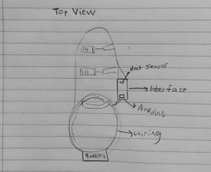
No matter how thick the socks and no matter how many foot warmers you stuff into your ski boot, there are some days when the conditions are just too brittle for comfort. We aim to solve this by developing a ski boot heater in which a battery pack fitted to the boot powers up two heating pads, one on the top of the foot and the other on the toes, meshed within the boot. And to ensure customization and to combat overheating, there will be a temperature gauge the user may interact with to adjust the temperature to his/her liking. This interface will also be fixed to the boot, and have thickness so that it may double as an encasing for the Arduino, circuits and breadboard. Each heating pad will be linked to a LED button, which lights up when clocked on, and an accompanying dial under each button to allow for the user to manually adjust the warmth of each pad. A row of 4-6 LED's will be located at the top of the interface to illustrate how hot each pad is.
Objectives
- To create an efficient closed loop system between the battery pack and heat pad that does not lose power[1]
- To prevent the boot from overheating
- To ensure that the panel boot warming system is waterproof and unaffected by the elements
- To create an efficient and elegant user interface that will allow for the wearer to control the temperature of each heating pad.[2]
Challenges
- Learning how to use Arduino in creating a user interface for temperature control
- Ensuring the general safety of our design, by eliminating exposed wires and ensuring a limited amount of current is supplied to the heat pads so that they do not overheat
- Encasing all exposed electrical components to not only make the product look more polished, but more importantly, to ensure the system is waterproof
- Learning how to 3-D print to create encasings for the interface and any exposed electrical components
- Ensuring there is enough voltage in our battery pack to power the heating pad, without compromising comfort or functionality of the ski boot
- Further down the road, we would like to see if we can add a solar panel component to our system as an additional means of charging the battery. Should we tackle this, figuring out how to attach the solar panel onto the ski in a way that is both strong yet matches the ski’s flexibility will be another challenge.
Initial Design Sketches
| Exterior | Interior | Top Down |
|---|---|---|
Gantt Chart
Budget
- Filament for 3d printer (provided)
- Arduino (provided)
- 5V heating pads (x2)- $9.90 ($4.95 each) https://www.sparkfun.com/products/11289
- Assorted LED Pack - $2.95 https://www.sparkfun.com/products/12062
- LED Tactile Button (x2) - $3.90 ($1.95 each) https://www.sparkfun.com/products/10443
- Silver Metal Knob (x2) - $3.00 ($1.50 each) https://www.sparkfun.com/products/10001
- N Channel MOFSET (x2)- $1.90 ($0.95 each) https://www.sparkfun.com/products/10213
- Diode 10 pack-$1.50 https://www.adafruit.com/products/755
- 10K ohm resistor 20 pack-$0.95 https://www.sparkfun.com/products/11508
- Digital Temperature Sensor Breakout (x2) -$9.90 ($4.95 each) https://www.sparkfun.com/products/13314
- 330 ohm resistor 30 pack- $0.95 https://www.sparkfun.com/products/11507
- Ski boots - $10 https://stlouis.craigslist.org/spo/5966731361.html
- 9V batteries - $8.79 https://www.amazon.com/gp/product/B0164F986Q/ref=ox_sc_act_title_1?ie=UTF8&smid=A192YN97ZBIJZL&th=1
- 9V Wall Adapter Power Supply - $5.95 https://www.sparkfun.com/products/298
- Adafruit 9V Battery Case w/ Switch and Barrel Connector - $3.95 http://www.robotshop.com/en/adafruit-9v-battery-case-switch-barrel-connector.html?gclid=CjwKEAiAlZDFBRCKncm67qihiHwSJABtoNIg8UX8WD3DJWL1M7AK0-IAY6HTO1l_bPe_HL9vlP54MRoCKuPw_wcB
- Gorilla Epoxy - $5.47 https://www.amazon.com/Gorilla-Epoxy-85-oz-Clear/dp/B001Z3C3AG
- Rotary Potentiometer 10k Ohm, Linear (x2) - $1.90 ($.95 each) https://www.sparkfun.com/products/9939
- Solderable Perf Board, 2-1/2 x 3-1/8" - $4.05 ($1.35 each) https://www.circuitspecialists.com/64-8933.html
Total: $71.01
Design + Solutions
How To: Create a Flashy, Blinking Turn-On Sequence for a Button with LEDs
Initially, we were going to use nifty buttons with built-in LEDs to indicate that the system was on and running, but unfortunately we found that the leads for the LED part of the button were super flimsy and would turn would break easily upon soldering. So we had to think creatively to come up with another to indicate to the user that the system was turned on in the interface, so we turned our attention to the row of LEDs already being used to indicate the heat level of the pads. With quite a bit of ease, we were able to have them blink in fun sequence in response to the button being pressed. Now, allow us to teach you how to do the same!
Materials: Arduino Mega board, Tactile pushbutton (easily found on Sparkfun), one 10kΩ resistor, four 220Ω resistors, 4 LEDs, wires
Step 1: Connect the button. This we took directly from Arduino’s tutorial, which can be found here (the resistor seen is a 10kohm resistor). The placement of the button pin is up to you, as long as it is connected to a digital pin.
Step 2: Now time for the coding! It is a very simple bit of code, which is can be found here. Read through the comments to get a full understanding of it, and make sure that the declaration of buttonPin matches the digital pin on the Arduino that your button is connected to.
Step 3: Now that the button is connected to the board, it is time to add our LED lights, along with their resistors. For our project, we used 4, as seen in the circuit diagram.
Make sure that at the end of each LED resistor, a wire runs from a pin parallel to the resistor lead and into a digital pin on the Arduino Mega.
Step 4: More code! You can find it here, but we are really just building off the original button code, only with a couple additions:
- Initialization of the LEDs onto the Arduino (same as for the button)
- Declaring the LEDs as “Outputs” in the void setup (as the button is declared as an Input)
- Including a for loop inside the if statement portion in which the button and system are turned on.
- Once the for loop conditions are set, the blinking sequence is really up to you. Just write “digitalWrite(led_, HIGH) to turn the LED of your choice on, and add a very small delay in between the next course of action
- Also make sure to include “digitalWrite(led_, LOW)” for each LED under the else if condition where the system is off, just to ensure that every light is off when the system is off
And that’s it - go blink away!
How To: Control a Series of LEDs with a Potentiometer
How To: Control a Heat Pad with a MOSFET and Potentiometer
How To: Connect Multiple TMP102 Sensors to One Arduino Mega
References
- ↑ Coding Heating Pads with Arduino Uno, https://astronomersanonymous.wordpress.com/2016/04/02/controlling-heating-pads-with-arduino-uno/
- ↑ Make Your Own Temperature Controller with an Arduino http://www.makeuseof.com/tag/make-your-own-temperature-controller-with-an-arduino/


