Mini-Studio: Motors
Background
This mini-studio is intended to introduce some of the other components of the Maker Kit that may be useful for projects.
Objectives
The objectives of today’s Studio are:
- Practice using a hobby Servo
- Practice using a transistor to turn on a motor (pancake/vibration motor)
1. Studio Setup
As usual, you should work in a group. Your usual group of four is desirable, but not required. Today’s studio checkout will be performed by TAs. There is no GitHub repo to get/commit.
2. Studio: Servos, Motors, and Transistors
2.1. Debrief
Take five minutes and summarize what you collectively know about:
- Hobby servos
- Transistors (particularly NPN transistors)
- DC Motors
2.2 Hobby Servo Tests
A servo is one type of motor used in a lot of interesting projects. This type of servo included in your Photon kit is commonly used in projects where back-and-forth motion is needed.
- Remove the Servo from the box (labelled ES08A). The motor shaft is connected to a small white gear on the top.
- The box includes several “horns” (white plastic pieces that fit onto the gear). Put the largest horn on the shaft of the motor. Usually a screw is used to ensure the horn doesn’t come off, but is isn’t necessary for today’s tests.
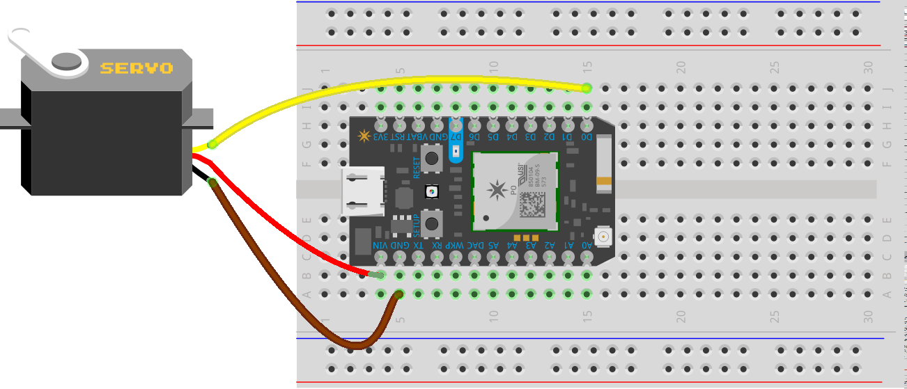
- The Hobby Servo included in the Photon kit follows the JR color codes. Use the jumper wires in the Photon kit to connect between the plug on the servo and a socket on the breadboard (the jumper wires have a wire exposed on both sides of the wire).
- The Brown wire is the ground and should be connected to the
GNDpin - The Red wire is the power supply and should be connected to the
VINpin - The Yellow wire is the signal. It can be connected to any of the digital pins (
D0-D7), but useD0.

Most Arduino-based libraries, including the one used in the Photon, include support for servos like this.
Run the following code:
// Declare a servo object:
Servo servo;

void setup() {
  Serial.begin(9600);
  servo.attach( D0 );
  servo.write( 20 );
}

void loop() {
  delay(1000);
}
2.3 Hobby Servo Experiments
Try some experiments. You may want to refer to the Particle API’s Servo documentation.
2.3.1 Experiment 1: Servo “Return to position”
When the preceding code is running, try to gently move the horn of the servo away from it’s position. What happens? (Be prepared to discuss with a TA)
2.3.1 Experiment 1: Range
Try to identify the range of your servo. Note the behavior at the “ends” of the range may seem unusual. What do you think is happening? (Be prepared to discuss with a TA)
2.3.2 Experiment 2: Detaching
Change the setup() (don’t change loop()) so it:
attaches to the servo.write(40)delay(2000)detaches from the servo
When the code is running, again try to gently move the horn of the servo away from it’s position. What happens? (Be prepared to discuss with a TA)
2.4 Vibration Motor Experiments
Small vibration motors are commonly used for Haptic Feedback in wearables and IoT devices.
Connect an LED to the Photon with a 220 Ohm resistor. Write a small sketch to blink the LED (Off for 1s, then On for 1s). Replace the LED with the Pancake Vibration Motor (Unlike the LED, the motor isn’t polarized, so it doesn’t really matter which wire is connected to the lower voltage part of the circuit)
The motor’s wires are extremely small and fragile. You may need to connect wires to the breadboard and then have one of your group members hold the bare end of the motor’s wires to a bare end of the wires to the breadboard. (Or trim back the insulation and wrap the wire around one post of a normal plug-in-wire)
This is an tolerable approach to quickly demonstrate the vibration motor’s general feel, but it isn’t running the motor at it’s full power. Moreover, DC motors should include a flyback diode to prevent a voltage spike due to stopping the current (and the coil of wire in the motor’s electromagnet, which is an inductor and tries to oppose this change). To achieve full power without exceeding your Arduino’s ability to supply current, build the circuit described at Learning About Electronic’s Vibration Motor Circuit. The Maker Kit contains all the parts you need:
- 0.1uF Capacitor
- NPN Small Signal Transistor (The part number is shown faintly on it. Be Careful! The Kit also comes with a temperature sensor that has the same size/shape. Read the part number on the package!)
- 1N4004 Diode
- 1k Ohm Resistor
A more thorough treatment of using Arduinos and other microcontrollers to control simple DC motors is given in Gerald Recktenwald’s Basic DC Motor Circuits.
3. In-Class Checkout
- Show a TA your progress
4. Post-Class Checkout
None for this!