When you choose Cell from the Create Partition dialog box, the Method list displays the following methods for partitioning cells:
Partition a cell by cutting it with a plane; the plane will pass completely through the cell. Use one of the following three methods to define the cutting plane:
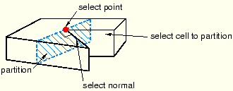
Select a point on the cutting plane; then pick an edge or datum axis that defines the normal to this plane, as shown in Figure 44–14.
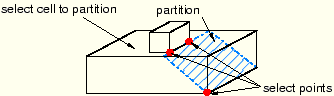
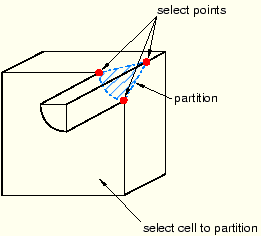
Select three distinct and noncolinear points, as shown in Figure 44–15.
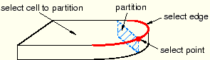
Select an edge and a point along the edge; the cutting plane will be normal to the edge at the selected point, as shown in Figure 44–16.
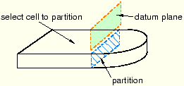
Partition a cell using the intersection with the extension of a datum plane, as shown in Figure 44–17. For detailed instructions, see “Using the datum plane method to partition cells,” Section 44.7.2.
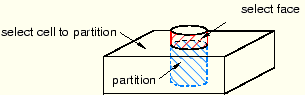
Partition a cell by cutting it with a shell, where the shell is the extended geometry of a face, as shown in Figure 44–18. The face being extended can be planar, cylindrical, conical, or spherical. For detailed instructions, see “Using the extended face method to partition cells,” Section 44.7.3.
Partition a cell by sweeping selected edges (that form the sweep profile) along a selected path (known as the sweep path). You can select any number of edges to be swept, although all the edges must be connected, must lie on the same plane, and must belong to the same part instance.
Use either of the following two methods to define the sweep path:
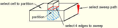
Create a straight partition through the cell by extending the sweep profile infinitely in a direction parallel to a selected straight edge or datum axis that acts as a sweep path; the partition is created where the swept edge(s) pass through the selected cell, as shown in Figure 44–19. The sweep path must be straight and perpendicular to the set of edges being swept.
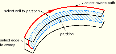
Create a straight or curved partition through the cell by extending the sweep profile along or parallel to a selected edge. The partition extends only as far as the selected edge; and the partition is created where the swept edge(s) pass through the selected cell, as shown in Figure 44–20. The sweep path must begin in the plane containing the edges to be swept, and its tangent must be perpendicular to the same plane.
Partition a cell by dividing it with a surface patch formed from a loop of connected edges. The edges can be curved or straight, must be connected, and must belong to the same part as the cell to be partitioned. In addition, the patch must pass completely through the cell. Choose from the following methods to define the patch:
Select Edges
You can choose from the following methods to select the edges that form the N-sided patch:
Loop
Select a single edge, and allow ABAQUS/CAE to search for a continuous loop of connected edges that will partition the cell, as shown in Figure 44–21. The resulting patch can have any number of edges.
Edges
Manually select the edges that will partition the cell. You can select any number of edges, and the selected edges must form a closed loop.
Select Corner Points
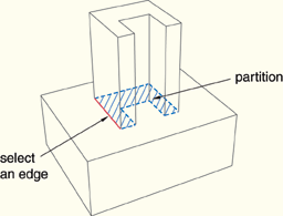
Select three, four, or five points that define the corners of the patch. If two of the points are connected by an existing edge, the resulting partition will follow the curve of the edge, as shown in Figure 44–22. The points must be on the boundary edges of the cell being partitioned.
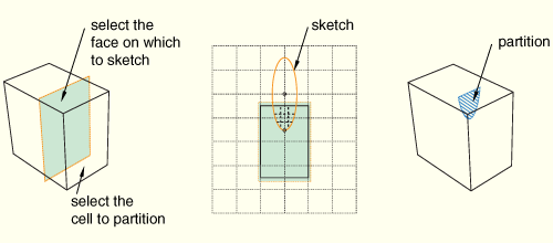
Partition a selected cell by sketching a partition with the Sketcher, as shown in Figure 44–23. In most cases you will sketch on a datum plane that intersects the selected cell. You can also select an existing face on which to sketch and draw the sketch outside the boundaries of the face. ABAQUS/CAE creates the partition wherever the sketch intersects the cell.
For detailed instructions, see “Using the sketch planar partition method to partition a cell,” Section 44.7.6.