
You can partition a selected cell by sketching the geometry of a planar partition using the Sketcher. You use the Sketcher when you want to create a partition whose shape cannot be achieved with any of the other partition tools. A sketched partition is useful for creating a crack face that will be used in a fracture mechanics analysis.
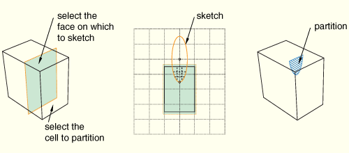
You must sketch on a planar face. In most cases you will sketch the partition on a datum plane that intersects the selected cell. The following figure illustrates a sketched planar partition on a datum plane:
To partition a cell using the sketch planar partition method:
From the main menu bar, select Tools![]() Partition.
Partition.
The Create Partition dialog box appears. ABAQUS/CAE displays prompts in the prompt area to guide you through the procedure.
Tip:
You can also use the sketch planar partition method to partition cells using the ![]() tool, located with the partition cell tools in the module toolbox. For a diagram of the partition tools in the toolbox, see “Using the Partition toolset,” Section 44.2.
tool, located with the partition cell tools in the module toolbox. For a diagram of the partition tools in the toolbox, see “Using the Partition toolset,” Section 44.2.
From the Type radio buttons at the top of the dialog box, choose Cell.
The Method list displays the methods that you can use to partition a cell.
From the list of methods, select Sketch planar partition and click Apply.
If the part or assembly contains only one cell, ABAQUS/CAE enters the Sketcher.
If the part or assembly contains more than one cell, select the cell to partition and click mouse button 2.
Tip:
If you are unable to select the desired cell, you can change the selection behavior by clicking the selection options tool ![]() in the prompt area. For more information, see “Using the selection options,” Section 6.3.
in the prompt area. For more information, see “Using the selection options,” Section 6.3.
Select the planar face on which to sketch. If no suitable face exists, you can select a datum plane.
The selected face is highlighted in the viewport.
Select an edge and the orientation of the edge on the Sketcher grid. The edge must not be perpendicular to the sketch plane. By default, the selected edge will appear vertical and on the right side of the Sketcher grid. To choose a different orientation for the edge, click the arrow on the right side of the dialog box and choose an orientation from the list that appears.
Tip: If the part or assembly does not have an edge that will provide the desired orientation, you can create a datum axis. You can then select the datum axis to control the orientation of the part on the Sketcher grid.
ABAQUS/CAE highlights the selected edge, enters the Sketcher, and rotates the part until the selected planar face or datum plane aligns with the plane of the Sketcher grid and the selected edge aligns with the grid in the desired orientation. ABAQUS/CAE highlights the selected faces.
Use the Sketcher to sketch the planar partition. From the main menu bar, click Done to indicate you have finished sketching the partition.
In the prompt area, click Create Partition.
ABAQUS/CAE creates the partition.
