In the Sketch module you can use mirrors and patterns to copy a common feature and complete the sketch of a feature. Similarly, in the Visualization module you can copy analysis results representing a repetitive portion of a model to visualize results for the entire model. To mirror results, you can select the coordinate system and up to three mirrors corresponding to the principal planes of the selected system. To pattern results, you can select the coordinate system and apply a rectangular or circular pattern. You can apply mirrors, rectangular patterns, and circular patterns in conjunction; and you can select their order of application to produce the desired view.
Note: There are no restrictions to prevent copied results from obscuring portions of the original data or other copies in the viewport.
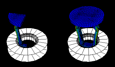
Figure 36–15 shows one quarter of a plastic fastener as it was modeled for analysis (left) and the same model mirrored about two symmetry planes to display the complete fastener (right). (The rigid hole is a swept profile and, thus, appears complete prior to mirroring the fastener.)
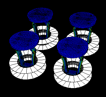
Figure 36–16 shows a rectangular pattern of completed fasteners.To mirror your model:
Locate the Mirror options.
From the main menu bar, select View![]() ODB Display Options. Click the Mirror/Pattern tab in the dialog box that appears. The Mirror options are in the upper portion of the page.
ODB Display Options. Click the Mirror/Pattern tab in the dialog box that appears. The Mirror options are in the upper portion of the page.
Accept the default global coordinate system, or select a coordinate system from the Mirror CSYS list.
You can select any coordinate system that exists in the output database. If a suitable coordinate system does not already exist, you can create a new coordinate system using one of the methods described in “Creating coordinate systems during postprocessing,” Section 24.7.
Toggle on the mirror planes that you want ABAQUS/CAE to use to copy the model results.
Toggle on Mirror display bodies if you also want ABAQUS/CAE to copy display bodies.
If you apply mirrors in conjunction with rectangular or circular patterns, select the Order of Operations that ABAQUS/CAE will use to create the copies.
Click Apply to implement your changes.
Your specifications are reflected in all plot states and are saved for the duration of the session.
If a contour plot is displayed, the contours appear on all faces.
If a symbol or material orientation plot is displayed, the symbols or material orientations appear only on the original model faces.
To pattern your model:
Locate the Pattern options.
From the main menu bar, select View![]() ODB Display Options. Click the Mirror/Pattern tab in the dialog box that appears. The Pattern options are in the middle of the page.
ODB Display Options. Click the Mirror/Pattern tab in the dialog box that appears. The Pattern options are in the middle of the page.
Accept the default global coordinate system, or select a coordinate system from the Pattern CSYS list.
You can select any coordinate system that exists in the output database. If a suitable coordinate system does not already exist, you can create a new coordinate system using one of the methods described in “Creating coordinate systems during postprocessing,” Section 24.7.
Edit the rectangular and circular pattern parameters as follows:
Rectangular pattern
Enter the Number of results that you want to display in the X-, Y-, and Z-directions of the selected coordinate system.
Enter the Offset distance, in model units, between copies for each direction.
To place the copies adjacent to each other, the offset in each direction must be the same as the model dimension in that direction.
Tip:
If you do not know the model dimensions, use the query tool ![]() to determine the distance between the first and last model nodes in the desired direction. (For more information, see “Querying the model,” Section 30.3.2.)
to determine the distance between the first and last model nodes in the desired direction. (For more information, see “Querying the model,” Section 30.3.2.)
Circular pattern
Select the axis of rotation.
Enter the Number of results that you want to display around the selected axis.
If desired, edit the Total angle ABAQUS/CAE will use to position the copies.
ABAQUS/CAE places the original result at 0°. All subsequent copies are positioned according to the Total angle divided by the Number of copies.
If you use both rectangular and circular patterns or if you use a pattern in conjunction with mirrors, select the Order of Operations that ABAQUS/CAE will use to create the copies.
Click Apply to implement your changes.
Your specifications are reflected in all plot states and are saved for the duration of the session.
If a contour plot is displayed, the contours appear on all faces.
If a symbol or material orientation plot is displayed, the symbols or material orientations appear only on the original model faces.