You can display axisymmetric models as planar, two-dimensional shapes or “sweep” the models through a specified angle, producing a three-dimensional visual effect. Similarly, you can view just the modeled sector of a cyclic symmetric structure or “sweep” the sector to see a specified portion of the entire model. (For more information on cyclic symmetric structures, see “Analysis of models that exhibit cyclic symmetry,” Section 10.3.3 of the ABAQUS Analysis User's Manual.) In addition, you can view two-dimensional models (or three-dimensional cylindrical rigid surfaces) as planar or extrude them to a specified depth, producing a three-dimensional visual effect. Sweeping and extruding are particularly useful for displaying contour plots of two-dimensional elements and contact surfaces.
Axisymmetric analytical rigid surfaces can be rotated about an axis (swept), as can the following elements: ACAXn, CAXn, CAXAn, CGAXn, DCAXn, DCCAXn, DSAXn, FAXn, MAXn, MGAXn, RAXn, SAXn, and SAXAn. Models that contain three-dimensional axisymmetric analytical rigid surfaces or CAXA elements are swept by default (the default start angle, end angle, and number of sectors vary depending on the model type). If the model contains both analytical rigid surfaces and CAXA elements, only the CAXA elements are swept by default. When you display boundary conditions for swept axisymmetric elements, symbols appear on only the original nodes and not on the swept nodes.
Cyclic symmetric models are not swept by default. When you display contours on a swept cyclic symmetric model, only nodal quantities can be contoured on the swept sectors; scalar, vector, and tensor quantities at integration points can be contoured only on the original sector.
You can extrude analytical rigid surfaces and all of the planar, two-dimensional solid elements in the ABAQUS library along the Z-direction. For a list of these elements, see “Two-dimensional solid element library,” Section 22.1.3 of the ABAQUS Analysis User's Manual.
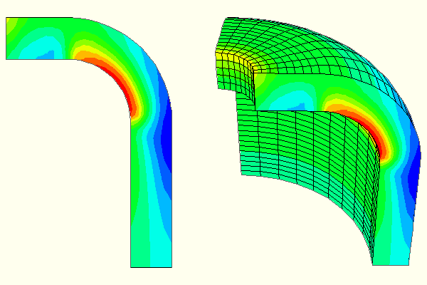
Figure 36–12 shows an axisymmetric planar model in a planar view (left) and the same model with an axisymmetric sweep angle of 90° and 10 sweep sectors (right).
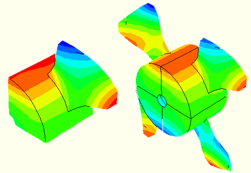
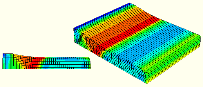
Figure 36–13 shows the original modeled sector of a cyclic symmetric fan (left) and sectors 1–4 of the swept model (right). Figure 36–14 shows a two-dimensional planar model in a planar view (left) and the same model displayed with an extrusion depth of 0.1 (right).To sweep elements in your axisymmetric model:
Locate the General Sweep options.
From the main menu bar, select View![]() ODB Display Options. Click the Sweep/Extrude tab in the dialog box that appears. The General Sweep options are in the upper portion of the page.
ODB Display Options. Click the Sweep/Extrude tab in the dialog box that appears. The General Sweep options are in the upper portion of the page.
Note: If there are no elements or analytical rigid surfaces in your model that can be swept, the General Sweep options will not be available.
Toggle Sweep elements.
Specify the sweep angle by typing a number (in degrees) in the Sweep from field (the default is 0°) and a number (in degrees) in the To field (the default is 180° for all models).
ABAQUS/CAE sweeps the two-dimensional model counterclockwise about the axis of rotation from the first specified angle to the second.
Specify the number of segments to use along the circumferential direction when sweeping by typing a positive integer in the Number of segments field or by clicking on the arrows next to the field. The default number of segments used varies depending on the model type.
The angle between the segments is updated automatically in the dialog box. As you increase the number of segments, curves in the model appear smoother (the angle between them decreases). However, a smaller number of segments plots faster.
Click Apply to implement your changes.
Your sweep specifications are reflected in all plot states and are saved for the duration of the session.
If a contour plot is displayed, the contours appear on all swept faces.
If a symbol plot is displayed, the model is swept as specified, but the symbols appear only on the original planar model faces.
To sweep analytical rigid surfaces in your axisymmetric model:
Locate the General Sweep options.
From the main menu bar, select View![]() ODB Display Options. Click the Sweep/Extrude tab in the dialog box that appears. The General Sweep options are in the upper portion of the page.
ODB Display Options. Click the Sweep/Extrude tab in the dialog box that appears. The General Sweep options are in the upper portion of the page.
Note: If there are no elements or analytical rigid surfaces in your model that can be swept, the General Sweep options will not be available.
Toggle on Sweep analytical rigid surfaces if it is not currently active.
Specify the sweep angle by typing a number (in degrees) in the Sweep from field and a number (in degrees) in the To field (the default value is 180° when you first open an axisymmetric model and 360° when you first open a three-dimensional model).
ABAQUS/CAE sweeps the analytical rigid surface counterclockwise about the axis of rotation from the first specified angle to the second.
Specify the number of segments to use along the circumferential direction when sweeping analytical rigid surfaces by typing a positive integer in the Number of segments field or by clicking on the arrows next to the field. By default, ABAQUS/CAE uses 10 segments for axisymmetric models and 20 segments for three-dimensional models.
The angle between the segments is updated automatically in the dialog box. As you increase the number of segments, curves in the model appear smoother (the angle between them decreases). However, a smaller number of segments plots faster.
Click Apply to implement your changes.
Your sweep specifications are reflected in all plot states and are saved for the duration of the session.
To sweep your cyclic symmetric model:
Locate the Sector Sweep options.
From the main menu bar, select View![]() ODB Display Options. Click the Sweep/Extrude tab in the dialog box that appears. The Sector Sweep options are in the center portion of the page.
ODB Display Options. Click the Sweep/Extrude tab in the dialog box that appears. The Sector Sweep options are in the center portion of the page.
Note: If there are no cyclic symmetry elements in your model, the Sector Sweep options will not be available.
Toggle Sweep cyclic symmetry sectors.
Click the arrow next to the Sector selection field to choose from the following available sweep methods:
By Number
This is the default sweep method. The total number of sectors in the model is given in the dialog box. You can specify which of these sectors should be displayed by typing positive integers between 1 and the total number of sectors (delimited by commas) in the Sectors field. The sectors are numbered counterclockwise from the original sector.
ABAQUS/CAE displays only the specified sectors (whether or not they are adjacent).
By Angle
The sector angle (the angle between each sector) is given in the dialog box. You can specify the sweep angle in increments of the sector angle by typing a number (in degrees) in the Sweep from field (the default is 0°) and a number (in degrees) in the To field (the default is the sector angle). Both numbers should be divisible by the sector angle.
Tip: You can also use the arrows next to the text fields to specify the angles.
ABAQUS/CAE sweeps the two-dimensional model about the axis of rotation by the number of degrees you specify. If you enter a sweep angle that is not divisible by the sector angle, ABAQUS/CAE rounds up to the next number that is.
All Sectors
If you choose this sweep method, all sectors will be displayed; in other words, the model will be swept 360° about the axis of rotation.
Click Apply to implement your changes.
Your sweep specifications are reflected in all plot states and are saved for the duration of the session.
If a contour plot is displayed, the contours of nodal quantities appear on all swept faces; contours of scalar, vector, and tensor quantities at integration points appear only on the original sector.
If a symbol plot is displayed, the model is swept as specified, but the symbols appear only on the original planar model faces.
To extrude elements in your model:
Locate the Extrude options.
From the main menu bar, select View![]() ODB Display Options. Click the Sweep/Extrude tab in the dialog box that appears. The Extrude options are in the lower portion of the page.
ODB Display Options. Click the Sweep/Extrude tab in the dialog box that appears. The Extrude options are in the lower portion of the page.
Note: If there are no elements in your model that can be extruded, the Extrude options will not be available.
Toggle Extrude elements.
When Extrude elements is on, the Depth option becomes available.
Specify the depth of the extrusion by typing a positive number (in model units) in the Depth field. The default depth is 1.0.
ABAQUS/CAE extends your model the specified number of units in the negative z-direction.
Use the view manipulation rotation tool to view the extruded model in three dimensions.
Click Apply to implement your changes.
Your extrude specifications are reflected in all plot states and are saved for the duration of the session.
If a contour plot is displayed, the contours appear on all extruded faces.
If a symbol plot is displayed, the model is extruded as specified, but the symbols appear only on the original planar model faces.
To extrude analytical rigid surfaces in your model:
Locate the Extrude options.
From the main menu bar, select View![]() ODB Display Options. Click the Sweep/Extrude tab in the dialog box that appears. The Extrude options are in the lower portion of the page.
ODB Display Options. Click the Sweep/Extrude tab in the dialog box that appears. The Extrude options are in the lower portion of the page.
Note: If there are no elements or analytical rigid surfaces in your model that can be extruded, the Extrude options will not be available.
Toggle on Extrude analytical rigid surfaces if it is not currently active.
When Extrude analytical rigid surfaces is on, the Depth options become available.
Select a depth for the extrusion.
You can either accept the default depth by selecting Auto-compute, or you can specify a custom depth by typing a positive number (in model units) in the Specify field. The default extrusion depth for analytical rigid surfaces is the maximum value that does not stretch the bounding box.
ABAQUS/CAE extends your model the specified number of units in the negative z-direction.
Use the view manipulation rotation tool to view the extruded model in three dimensions.
Click Apply to implement your changes.
Your extrude specifications are reflected in all plot states and are saved for the duration of the session.