You can use the following procedure to create a model with cohesive elements using geometry and mesh tools:
In the Part module, define the geometry of the model. You should define the geometric region that represents the cohesive layer as a solid, even if the thickness of the layer is close to zero. To avoid numerical problems, it is recommended that you model the geometry using a value of 10–4 or greater for the thickness. If the actual thickness of the layer is less than this value, you should specify the actual thickness in the Initial thickness field of the cohesive section editor as described in “Creating cohesive sections,” Section 12.11.10
In the Mesh module, mesh the surrounding bulk material. You can use any of the mesh tools to mesh the surrounding bulk material. See “Mesh generation,” Section 17.3.3, for more information.
In the Mesh module, mesh the cohesive region using one of the following methods:
Two- and three-dimensional models
Swept meshing technique. You can assign the swept meshing technique to mesh the cohesive region and choose a sweep path direction that is aligned with the thickness direction of the element. For a complex cohesive region, you may need to partition the model to create a group of sweep regions that you can align consistently. For more information, see “Selecting a meshing technique,” Section 17.16.3, and “Specifying the sweep path,” Section 17.16.6.
Three-dimensional models
Convert the cohesive region into a shell region, and use the offset meshing technique.
Convert the solid part to a shell using the From solid shell tool in the Part module.
Isolate a collection of faces that represents an idealized shell of the part using the Remove faces tool in the Repair toolset.
Mesh the simplified model with shell elements, and create an orphan mesh part.
Use the orphan mesh part to generate an offset mesh of solid hexahedral or wedge elements. The elements will be oriented through the thickness of the part, and you can verify this with the Query toolset.
In the Mesh module, use the element type assignment tool to assign the cohesive element type to the cohesive region. See “Element type assignment,” Section 17.5.3, for more information.
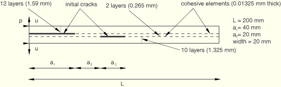
For example, Figure 21–1 illustrates the layered composite specimen that is used in the benchmark problem “Delamination analysis of laminated composites,” Section 2.7.1 of the ABAQUS Benchmarks Manual. An ABAQUS Scripting Interface script that reproduces the composite specimen model using ABAQUS/CAE is provided with this problem.