ABAQUS/CAE can use a variety of meshing techniques to mesh models of different topologies. In some cases you can choose the technique used to mesh a model or model region. In other cases only one technique is valid. The different meshing techniques provide varying levels of automation and user control.
Structured meshing
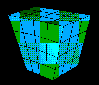
Structured meshing gives you the most control over your mesh because it applies preestablished mesh patterns to particular model topologies. Most unpartitioned solid models are too complex to be meshed using preestablished mesh patterns. However, you can often partition complex models into simple regions with topologies for which structured meshing patterns exist. Figure 17–3 shows an example of a structured mesh. For more information, see “Structured meshing and mapped meshing,” Section 17.8.
Swept meshing
ABAQUS/CAE creates swept meshes by internally generating the mesh on an edge or face and then sweeping that mesh along a sweep path. The result can be either a two-dimensional mesh created from an edge or a three-dimensional mesh created from a face. Like structured meshing, swept meshing is limited to models with specific topologies and geometries. Figure 17–4 shows an example of a swept mesh. For more information, see “Swept meshing,” Section 17.10.
Free meshing
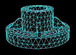
The free meshing technique is the most flexible meshing technique. It uses no preestablished mesh patterns and can be applied to almost any model shape. However, free meshing provides you with the least control over the mesh since there is no way to predict the mesh pattern. Figure 17–5 shows an example of a free mesh. For more information, see “Free meshing,” Section 17.9.
When the Mesh defaults color mapping is selected, ABAQUS/CAE uses different colors to indicate which meshing technique, if any, is currently assigned to a region. For example, if a solid region is meshable using the structured meshing technique, the region turns green when you enter the Mesh module; the green color indicates that the structured meshing technique is assigned to that region by default. If a region is unmeshable using the element shape currently assigned to it, the region turns orange when you enter the Mesh module.
You can change the applicable meshing techniques by partitioning the region into smaller regions with simpler topology or by changing the element shape assigned to that region.