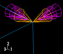
In many cases ABAQUS/CAE uses arrows to represent prescribed conditions in the viewport. These arrows represent each component of the prescribed condition. In general, the size of the arrows is uniform and unrelated to the magnitude of the prescribed condition. For loads that use the analytical field distribution option, the arrows are scaled based on the analytical field value. (For information on controlling arrow size and symbol scaling, see “Controlling the display of attributes,” Section 50.11.)
For example, the arrows that appear in Figure 16–6 represent the three components of a concentrated force that is applied to two vertices.
An arrow with a single arrowhead represents a component of a prescribed condition that is applied to a translational degree of freedom. For example, the three components of the concentrated force in Figure 16–6 are applied to degrees of freedom 1 through 3; therefore, each arrow in the figure has a single arrowhead.
When a component of a prescribed condition is applied to a rotational degree of freedom, that component appears as a double-headed arrow. The arrows in Figure 16–7 indicate that a Velocity/Angular Velocity boundary condition is applied to degrees of freedom 4 and 6 of the vertices.
A magnified view of the double-headed arrows appears in Figure 16–8.If you apply a prescribed condition to both translational and rotational degrees of freedom, both the single-headed and the double-headed arrows appear. For example, a Velocity/Angular Velocity boundary condition is applied to degrees of freedom 1, 3, 4, and 6 of the vertex in Figure 16–9.
Figure 16–9 Magnified view of a boundary condition applied to translational and rotational degrees of freedom.

For information on arrow color, see “Understanding prescribed condition symbol type and color,” Section 16.5.1. For information on when to expect arrows to point toward or away from a region, see “Understanding symbol location and direction,” Section 16.5.3.
