The type and color of the symbols that represent prescribed conditions can vary with
the type of prescribed condition that the symbols represent and
the degrees of freedom to which you apply the prescribed condition.
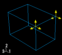
For example, Figure 16–3 displays a concentrated force applied to vertices. All of the arrows that represent the different components of the concentrated force are yellow.
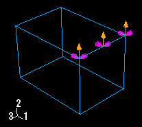
On the other hand, Figure 16–4 shows a Velocity/Angular Velocity boundary condition that is applied to both translational and rotational degrees of freedom. The sandy brown arrows represent components of the boundary condition that are applied to translational degrees of freedom. The magenta arrows represent components of the boundary condition that are applied to rotational degrees of freedom.
Note: When a boundary condition fixes a degree of freedom in place, the arrow representing that component lacks a stem.
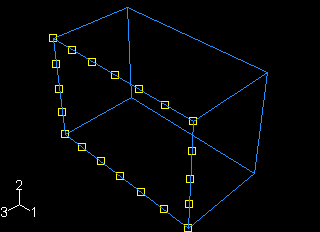
Figure 16–5 displays a uniform temperature field applied to a face.