Select Constraint Edge to Edge from the main menu bar to apply a constraint that positions a movable part instance so that a selected edge is parallel to a selected edge of a fixed part instance. In addition, if the part instances are two-dimensional, you must specify the distance between the selected edges; otherwise, ABAQUS/CAE makes them coincident. All position constraints are features of the assembly and can be suppressed or deleted using the Feature Manipulation toolset. In addition, you can edit the clearance between the two selected edges, where applicable. For more information, see “How the position constraint methods differ,” Section 13.4.2.
To constrain two part instances with parallel edges separated by a specified distance:
From the main menu, select Constraint Edge to Edge.
Tip:
You can also apply the edge-to-edge constraint using the ![]() tool in the Assembly module toolbox. For a diagram of the tools in the Assembly toolbox, see “Using the Assembly module toolbox,” Section 13.8.
tool in the Assembly module toolbox. For a diagram of the tools in the Assembly toolbox, see “Using the Assembly module toolbox,” Section 13.8.
ABAQUS/CAE displays prompts in the prompt area to guide you through the procedure.
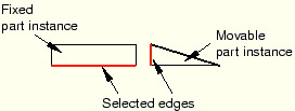
Select a straight edge from the part instance that will move and a straight edge from the part instance that will remain fixed, as shown in the following figure:

ABAQUS/CAE displays arrows along the selected edges.
When ABAQUS/CAE prompts you to select the edge from the fixed part instance, you can select a datum axis that was created in either the Part or Assembly module. In contrast, when you select the edge from the movable part instance, you can select a datum axis that was created only in the Part module.
From the buttons in the prompt area, do one of the following:
Click OK to accept the direction of the arrow along the edge of the movable instance.
Click Flip to reverse the direction of the arrow along the edge of the movable instance and click OK.
If the part instances are three-dimensional, ABAQUS/CAE positions the movable part instance so that the selected edges are parallel and coincident.
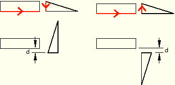
If the part instances are two-dimensional, you must specify the clearance between the selected edges. In the text field that appears in the prompt area, enter the distance from the edge of the movable part to the edge of the fixed part instance, positive along the normal to the edge of the fixed instance.
ABAQUS/CAE positions the movable part instance so that the two edges are parallel and the arrows point in the same direction. In addition, the movable part instance is translated to satisfy the clearance specified. The orientation of the fixed part instance remains unchanged. The effect of specifying the distance and changing the direction of the arrow is illustrated with two-dimensional instances in the following figure:

If the edge-to-edge constraint conflicts with existing constraints, ABAQUS/CAE displays an error message and cancels the operation. To avoid the conflict, you can try reversing the selection of the part instance that will move and the part instance that will remain fixed. Alternatively, you can convert the existing constraints to an absolute position and reapply the edge-to-edge constraint.
