A position constraint defines a relationship between two part instances—one that will move (the movable part instance) and one that will remain stationary (the fixed part instance). When you apply a position constraint, ABAQUS/CAE computes a position for the movable part instance that satisfies this relationship; you do not specify the position directly. You can apply the following position constraints to part instances in the Assembly module:
Parallel face (three-dimensional part instances only)
Face to face (three-dimensional part instances only)
Parallel edge
Edge to edge
Coaxial (three-dimensional part instances only)
Coincident point
Parallel coordinate systems
The definition of a constraint feature includes all the faces and edges that you originally selected. If you subsequently modify a part or move a part instance, ABAQUS/CAE automatically recalculates the constraint based on your original selection of faces and edges. As a result, one or more part instances may move after the assembly is regenerated. For example, different edges may become parallel. For more information on features, see “Manipulating features in the Assembly module,” Section 13.7.2, and Chapter 42, “The Feature Manipulation toolset.”
The following position constraints are provided by the Assembly module:
Parallel Face
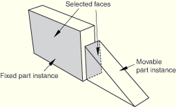
A parallel face position constraint causes a selected face of the movable part instance to become parallel with a selected face of the fixed part instance. However, the position constraint does not specify the precise location of the movable part instance, and the distance between the parallel faces is arbitrary. To apply a parallel face position constraint between two part instances, you do the following:
Select the faces to be constrained to be parallel from the movable part instance and the fixed part instance, as shown in Figure 13–3.
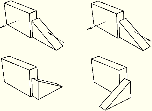
ABAQUS/CAE displays arrows normal to the selected faces. You prescribe the orientation of the movable part instance by selecting the direction of the arrow normal to its selected face. Figure 13–4 illustrates the result of applying the position constraint and the effect on the movable part instance of reversing the direction of the arrow.
ABAQUS/CAE rotates the movable part instance until the two selected faces are parallel and the arrows are pointing in the same direction.Face to Face
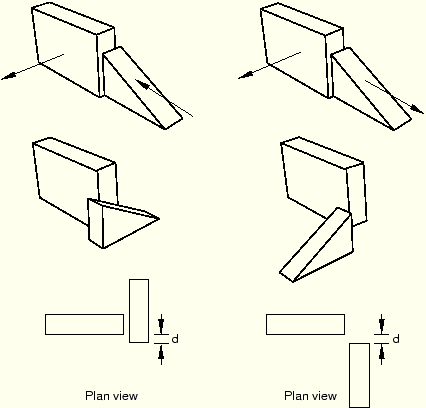
A face-to-face position constraint is similar to a parallel face position constraint except that you define the clearance between the parallel faces. The clearance is measured between the two selected faces, positive along the normal to the fixed part instance. Other than this clearance, the precise location of the movable part instance is not constrained. Assuming that you selected the same two faces shown in Figure 13–3, the effect of applying a face-to-face constraint is shown in Figure 13–5. Figure 13–5 also illustrates the effect on the movable part instance of reversing the direction of the arrow normal to its selected face.
ABAQUS/CAE rotates the movable part instance until the two selected faces are parallel and the arrows point in the same direction. In addition, the movable part instance is translated to satisfy the clearance specified. The faces you select from the movable and fixed part instances must be planar. The face-to-face position constraint can be applied only to three-dimensional part instances.Parallel Edge
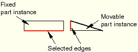
A parallel edge position constraint causes a selected edge of the movable part instance to become parallel with a selected edge of the fixed part instance. However, the position constraint does not specify the precise location of the movable part instance, and the distance between the parallel edges is arbitrary. To apply a parallel edge position constraint between two part instances, you do the following:
Select the edges to be constrained to be parallel from the movable and fixed part instance, as shown in Figure 13–6.
ABAQUS/CAE displays arrows along the selected edges. You prescribe the orientation of the movable part instance by selecting the direction of the arrow along its selected edge. Figure 13–7 illustrates the result of applying the position constraint and the effect on the movable part instance of reversing the direction of the arrow.
ABAQUS/CAE rotates the movable part instance until the two selected edges are parallel and the arrows point in the same direction.Edge to Edge
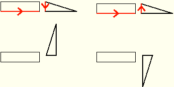
An edge-to-edge position constraint is similar to a parallel edge position constraint except that the clearance between the parallel edges is defined by the constraint. Assuming that you selected the same two edges shown in Figure 13–6, the effect of applying an edge-to edge position constraint to a two-dimensional assembly is shown in Figure 13–8. Figure 13–8 also illustrates the effect on the movable part instance of reversing the direction of the arrow along its selected edge.
Figure 13–8 The result of applying an edge-to-edge constraint and the effect of changing the direction of the arrow along the selected edge of the movable part instance.
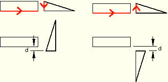
If the assembly is three-dimensional, ABAQUS/CAE positions the movable part instance so that the edges are coincident.
If the assembly is two-dimensional, you can specify the clearance between the selected edges. The clearance is measured between the two selected edges, positive along the normal to the fixed part instance.
Coaxial
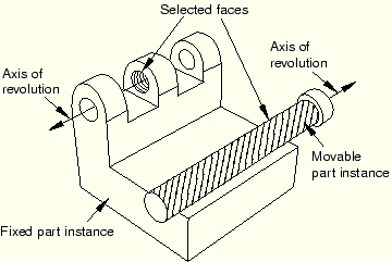
A coaxial position constraint causes a selected cylindrical or conical face of the movable part instance to become coaxial with a selected cylindrical or conical face of the fixed part instance. However, the coaxial position constraint does not constrain the precise location of the movable part instance. To apply a coaxial position constraint between two part instances, you do the following:
Select the cylindrical or conical faces to be constrained to be coaxial from the movable and fixed part instance, as shown in Figure 13–9.
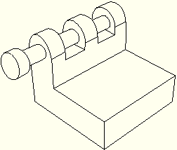
ABAQUS/CAE displays arrows along the axis of revolution of the selected part instances. You prescribe the orientation of the movable part instance by selecting the direction of the arrow along its axis of revolution. Figure 13–10 illustrates the result of applying the coaxial position constraint.
Coincident Point
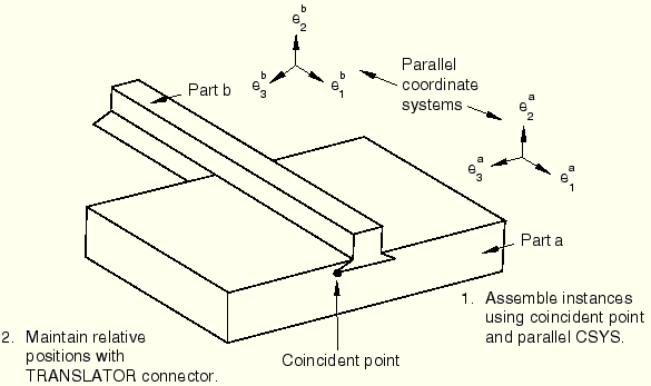
A coincident point constraint causes a selected point on the movable part instance to coincide with a selected point on the fixed part instance. However, the coincident point constraint does not constrain the orientation of the movable part instance. The orientation of the movable part instance does not change after the constraint is applied, as shown in Figure 13–11. For detailed instructions, see “Constraining two part instances with coincident points,” Section 13.10.7.
Parallel CSYS
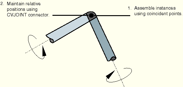
A parallel coordinate systems constraint causes the axes of a datum coordinate system on the movable part instance to become parallel with the axes of a datum coordinate system on the fixed part instance. However, the parallel coordinate systems constraint does not specify the precise location of the movable part instance. Figure 13–12 illustrates the effect of applying a parallel coordinate systems constraint and a concident point constraint to two part instances.
The coordinate systems can be either rectangular (X-, Y-, and Z-axes), cylindrical (R-,You can use datums to position part instances. When you are prompted to select a face, you can also select a datum plane. When you are prompted to select an edge, you can also select a datum axis or one of the axes of a datum coordinate system. You can select a datum that you created in the Part because the datum is associated with an instance of the part and moves with the part instance. However, if the position constraint uses a datum that you created in the Assembly module by selecting from a part instance (such as a face of a part instance), ABAQUS/CAE changes its regeneration behavior and regenerates features in the order that you created them. For more information, see “How are position constraints regenerated?,” Section 42.3.5. You cannot select a datum as the movable part instance if you created the datum in the Assembly module and it depends on more than one part instance; for example, a datum axis that runs through vertices of two part instances.