
You can add a point-to-point wire feature to a part or to an assembly. Assembly-level wire features are nonmeshable. The wire feature contains wires connecting points from the part or assembly in the current viewport or connecting points from the part or assembly to ground. To model connectors you must define one or more point-to-point wire features on your assembly. When you create a wire feature on a part or an assembly, you can create a geometry set that includes the wires defined in the wire feature. In addition, when you create a wire feature on a part, you can create geometry sets that include the vertices defined in the wire feature.
To add a wire feature on a part, select Shape![]() Wire
Wire![]() Point to Point from the main menu bar in the Part module. The point-to-point wire tool is always available in the Part module, regardless of the modeling space of the part in the current viewport. To add a wire feature on an assembly, select Connector
Point to Point from the main menu bar in the Part module. The point-to-point wire tool is always available in the Part module, regardless of the modeling space of the part in the current viewport. To add a wire feature on an assembly, select Connector![]() Geometry
Geometry![]() Point-to-Point Wire from the main menu bar in the Interaction module.
Point-to-Point Wire from the main menu bar in the Interaction module.
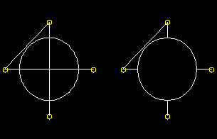
You add a point-to-point wire feature to a part or assembly by choosing a point selection method and picking points to connect from the current part or assembly. You can choose to select disjointed points (i.e., not automatically connected end-to-end), chained points (i.e., automatically connected end-to-end), or points that are connected to ground. ABAQUS/CAE connects the point pairs with a straight line or connects the points to ground depending on the method that you select. A wire feature connecting four points in a part is illustrated in the following figure:
During creation of the wire feature on a part or assembly, you can modify the point selections; however, once you have created the wire feature, you cannot modify it directly. If you want to change the points that are connected or the connection order, you must delete the wire and create a new wire connecting the desired points. For part-level wire features, since the point-to-point wire is dependent on points created by other features, you can modify the wire by using the Feature Manipulation toolset to modify the features that created the points. For assembly-level wire features you can remove wires from the feature (see “Creating wire features to define connector geometry,” Section 15.11.5, for more information).
Although you cannot create a part with a nonplanar wire base feature, you can create a nonplanar point-to-point wire feature by using a single point in space as the base feature and entering coordinates for the remaining points. In this case the starting point is the only point that you can edit to modify the wire. You can also use datum points, in which case you can edit all points.
To add a point-to-point wire feature to a part or assembly:
Display the Create Wires dialog box using one of the following methods:
From the main menu bar in the Part module, select Shape![]() Wire
Wire![]() Point to Point.
Point to Point.
Tip:
You can also add a point-to-point wire feature to a part using the ![]() tool, located with the wire tools in the Part module toolbox. For a diagram of the tools in the Part module toolbox, see “Using the Part module toolbox,” Section 11.17.
tool, located with the wire tools in the Part module toolbox. For a diagram of the tools in the Part module toolbox, see “Using the Part module toolbox,” Section 11.17.
From the main menu bar in the Interaction module, select Connector![]() Geometry
Geometry![]() Point-to-Point Wire.
Point-to-Point Wire.
Tip:
You can also add a point-to-point wire feature to an assembly using the ![]() tool, located in the Interaction module toolbox. For a diagram of the tools in the Interaction module toolbox, see “Using the Interaction module toolbox,” Section 15.10.
tool, located in the Interaction module toolbox. For a diagram of the tools in the Interaction module toolbox, see “Using the Interaction module toolbox,” Section 15.10.
In the Point Pairs portion of the dialog box, specify the point selection method.
Select Disjoint wires to select points that are not automatically connected end-to-end. Use this method to specify wires to use for modeling connectors (see “Overview of connector modeling,” Section 21.3.1). The first two points that you select become Point 1 and Point 2, respectively, of a point pair; the next two points that you select become Point 1 and Point 2, respectively, of the next point pair; and so on.
Select Chained wires to select points that are automatically connected end-to-end. The first point that you select becomes Point 1 of a point pair, the second point that you select becomes Point 2 of that point pair and Point 1 of the next point pair, and so on.
Select Wires to ground to select points that are connected to ground. Use this method to specify point-to-ground wires to use for modeling connectors (see “Overview of connector modeling,” Section 21.3.1). ABAQUS/CAE automatically makes each point that you select Point 2 of a point pair (i.e., Point 2 is connected to ground). However, you may want to connect Point 1 to ground. If so, you can modify the wire definition after you complete the point selection. Select the row number of the point pair that you want to modify, and click Swap to exchange the entries for Point 1 and Point 2 (as described in Step 5).
In the Point Pairs portion of the dialog box, click Add to select the points that the wire will connect.
If you are adding a wire feature to a part, you can select points from the viewport or you can enter the coordinates in the text box in the prompt area. ABAQUS/CAE highlights all the points that you can pick. The possible choices are:
Vertices
The midpoints of lines and arcs
The centers of circles and arcs
Datum points
If you are adding a wire feature to an assembly, you can select points from the viewport. ABAQUS/CAE highlights all the points that you can pick. The possible choices are:
Vertices or nodes
Reference points
ABAQUS/CAE displays prompts in the prompt area to guide you through the procedure.
Tip:
If you are unable to select the desired points, you can change the selection behavior by clicking the selection options tool ![]() in the prompt area. For more information, see “Using the selection options,” Section 6.3.
in the prompt area. For more information, see “Using the selection options,” Section 6.3.
As you select points, ABAQUS/CAE displays a representation of the completed point-to-point wire based on your current selections highlighted in red.
When you have finished selecting points, click Done in the prompt area.
The Create Wires dialog box reappears. The points that you selected to define the wire are listed in the Point Pairs table.
From the Point Pairs table, you can do the following:
To add more point pairs, repeat Steps 2 through 4. The representation of the added point-to-point wire is highlighted in magenta.
To edit a point, select the point in the table, click Edit, and reselect a point. The selection highlighting in the viewport is updated to show the newly edited point.
To identify a specific point pair in the viewport, select the desired row number. The line connecting the selected point pair is highlighted in magenta.
To remove a point pair, select the desired row number and click Delete.
To exchange the entries for Point 1 and Point 2 in a point pair, select the desired row number and click Swap.
If you are adding a wire feature to a part, ABAQUS/CAE creates the entire point-to-point wire by default, regardless of where it passes through or across existing part faces. If you want to create the wire feature only where it extends beyond the faces of the part, toggle on Merge wire with part geometry. The Merge wire with part geometry option is available only in the Part module.
In the Set Creation portion of the dialog box, do the following:
Toggle on Create set of wires if you want ABAQUS/CAE to create a geometry set of wires.
Toggle on Create set of vertices if you want ABAQUS/CAE to create a geometry set of the Point 1 entries and a geometry set of the Point 2 entries in the wire definition. The Create set of vertices option is available only in the Part module.
Click OK to create the point-to-point wire feature.
Part-level wire features appear as solid lines in the viewport and appear in the Model Tree in the Features container under the part.
Assembly-level wires features are nonmeshable, appear as dashed lines in the viewport, and appear in the Model Tree in the Features container under the assembly.
