
Select Shape![]() Wire
Wire![]() Sketch from the main menu bar to add a sketched planar wire feature to the part in the current viewport. The planar wire tool is always available, regardless of the modeling space of the part in the current viewport.
Sketch from the main menu bar to add a sketched planar wire feature to the part in the current viewport. The planar wire tool is always available, regardless of the modeling space of the part in the current viewport.
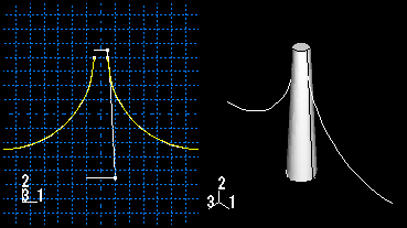
You add a planar wire feature by sketching the feature on a selected plane. ABAQUS/CAE removes any portion of the wire that overlaps an existing face. A sketch and the resulting planar wires are illustrated in the following figure:
To add a sketched wire feature:
From the main menu bar, select Shape![]() Wire
Wire![]() Sketch.
Sketch.
ABAQUS/CAE displays prompts in the prompt area to guide you through the procedure.
Tip:
You can also add a sketched wire feature using the ![]() tool, located with the wire tools in the Part module toolbox. For a diagram of the tools in the Part module toolbox, see “Using the Part module toolbox,” Section 11.17.
tool, located with the wire tools in the Part module toolbox. For a diagram of the tools in the Part module toolbox, see “Using the Part module toolbox,” Section 11.17.
If the modeling space of the part is two-dimensional or axisymmetric, ABAQUS/CAE enters the Sketcher and aligns the X- and Y-axes of the part and the sketch.
If the part is three-dimensional, do the following:
Select the planar face on which the wire will be positioned. If no suitable face exists, you can select a datum plane.
Tip:
If you are unable to select the desired planar face, you can change the selection behavior by clicking the selection options tool ![]() in the prompt area. For more information, see “Using the selection options,” Section 6.3.
in the prompt area. For more information, see “Using the selection options,” Section 6.3.
Select an edge and the orientation of the edge on the Sketcher grid. The edge must not be perpendicular to the selected face. By default, the selected edge will appear vertical and on the right side of the Sketcher grid. To choose a different orientation for the edge, click the arrow on the right side of the dialog box and choose an orientation from the list that appears.
Tip: If the edge of the selected face is curved or does not provide the desired orientation, you can create a datum axis. You can then select the datum axis to control the orientation of the part on the Sketcher grid.
ABAQUS/CAE highlights the selected edge, enters the Sketcher, and rotates the part until the selected face aligns with the plane of the Sketcher grid and the selected edge aligns with the grid in the desired orientation.
If you are unsure of the part's orientation relative to the Sketcher grid, use the view manipulation tools from the toolbar to view its position. Use the reset view tool ![]() to return to the original view.
to return to the original view.
Use the Sketcher to sketch the planar wire. In the prompt area, click Done to indicate you have finished sketching.
The part returns to its original orientation with the planar wire positioned on the selected face. The wire feature is created only where it extends beyond the faces of the part; a wire feature cannot overlap a face.
