
Select Shape![]() Solid
Solid![]() Loft from the main menu bar to add a solid loft feature to the part in the current viewport. You can add a solid loft feature only to three-dimensional parts.
Loft from the main menu bar to add a solid loft feature to the part in the current viewport. You can add a solid loft feature only to three-dimensional parts.
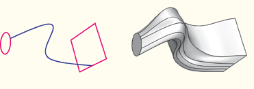
You add a solid loft feature by creating two or more sections from selected edges and by defining one or more loft paths. Loft sections, a loft path, and the resulting solid loft feature are illustrated in the following figure:
You can allow ABAQUS/CAE to define a single loft path using a smooth path to connect the center of each loft section. If you allow ABAQUS/CAE to define the path, you can apply tangency methods to the start and end sections of the loft. The curve and tangencies define the path of the loft feature between sections. Alternatively, you can define one or more loft paths by selecting curves that connect a point on each loft section to a point on the next loft section. Each loft path must provide a continuous line connecting each consecutive loft section. If a loft path is not smooth (if there is more than one tangent to any point along the path), ABAQUS/CAE will display an error message when you try to create the loft. For more information about loft sections, loft paths, and loft tangencies, see “What is lofting?,” Section 11.14.
Note:
You do not use the Sketcher while adding a loft feature. As a result, all of the edges that define the loft sections and the loft paths must exist in the part geometry before you create the loft. To create a loft path or to create a nonplanar loft section, you can use the ![]() tool, located with the wire tools in the Part module toolbox (see “Adding a spline wire feature,” Section 11.23.3, for more information).
tool, located with the wire tools in the Part module toolbox (see “Adding a spline wire feature,” Section 11.23.3, for more information).
To add a solid loft feature:
From the main menu bar, select Shape![]() Solid
Solid![]() Loft.
Loft.
ABAQUS/CAE displays prompts in the prompt area to guide you through the procedure.
Tip:
You can also add a solid loft feature using the ![]() tool, located with the solid tools in the Part module toolbox. For a diagram of the tools in the Part module toolbox, see “Using the Part module toolbox,” Section 11.17.
tool, located with the solid tools in the Part module toolbox. For a diagram of the tools in the Part module toolbox, see “Using the Part module toolbox,” Section 11.17.
Create the loft sections by selecting edges from the part in the viewport. See “Creating loft sections,” Section 11.26.1, for detailed instructions on creating loft sections.
Toggle on Keep internal boundaries to maintain any faces or edges that are generated between the lofted solid feature and the existing part. The internal boundaries may create regions that can be structured or swept meshed without having to resort to partitioning.
When you have finished creating the loft sections, click on the Transition tab in the Edit Loft dialog box.
Do one of the following:
Click Select path to create the loft path (or paths) by selecting edges from the part in the viewport.
Click Specify tangencies to create the loft path (or paths) by using loft tangencies.
Click the Preview button in the Edit Loft dialog box.
ABAQUS/CAE displays a wireframe representation of the loft that would be created with your current settings.
If desired, you can add or remove loft sections, change the loft path definition method, or edit the loft tangency options to change the shape of the loft feature. Click Preview to see the effect of your changes in the viewport.
If desired, you can have ABAQUS/CAE test for self-intersection as it creates the loft feature. This test prevents creating a feature that would be difficult or impossible to mesh and analyze, but it becomes computationally expensive as the complexity of the loft feature increases. For more information, see “Self-intersection checks,” Section 11.14.4. To use self-intersection checks, select Feature![]() Options to open the Feature Options dialog box, and toggle on Perform self-intersection checks.
Options to open the Feature Options dialog box, and toggle on Perform self-intersection checks.
Click Done to create the loft and to close the Edit Loft dialog box.
If you choose to test for self-intersection and the test fails, the Edit Loft dialog box will reappear so that you can make changes. Otherwise, the solid loft feature is created in the viewport.
