You can sketch a two-dimensional profile and extrude it to create the following:
A three-dimensional extruded solid feature.
A three-dimensional extruded shell feature.
A three-dimensional extruded cut feature.
ABAQUS/CAE provides the following methods for defining the extrusion distance:
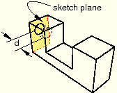
Blind
Specify the distance over which ABAQUS/CAE extrudes the sketch. The sketch and the distance define the feature and can be edited using the Feature Manipulation toolset. You can use this method when creating extruded solid, shell, and cut features. Figure 11–44 illustrates a blind extruded cut in a solid part.
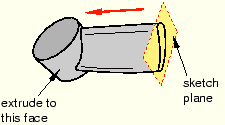
Up to Face
Select a single face to which ABAQUS/CAE extrudes the sketch. The selected face does not have to be parallel to the sketch plane. The selected face can be a nonplanar face; however, it must completely contain the extruded section. If you select this method to define the extrusion distance, only the sketch can be modified using the Feature Manipulation toolset; if you wish to extrude to a different face, you must create a new extruded cut feature. You can use this method when creating extruded solid, shell, and cut features. Figure 11–45 illustrates a sketch extruded to a nonplanar face.
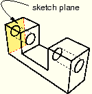
Through All
This method is available only for extruded cut features. ABAQUS/CAE extrudes the sketch defining the profile of the cut completely though the part. If you select this method to define the extrusion distance, only the sketch can be modified using the Feature Manipulation toolset. Figure 11–46 illustrates a through all cut in a solid part.