ABAQUS/CAE represents analytical rigid parts using profiles that are composed of a series of lines, arcs, and parabolas. Several tools are available in the Sketcher to help you construct each portion of the rigid part profile:
Lines
You use the Sketcher's Line tool to sketch straight lines.
Arcs and fillets
You use the Sketcher's Arc and Fillet tools to sketch circular arcs or to fillet two lines. Any resulting arcs must subtend an angle less than 180°; if you want to construct an arc subtending an angle greater than 180°, you should create two adjacent arcs. ABAQUS/CAE displays an error message if you create an arc subtending an angle greater than 180° while sketching the profile of an analytical rigid surface.
Splines
You use the Sketcher's Spline tool to sketch parabolas. You create a parabola by defining a three-point spline, where the three points are the start of the spline, a point anywhere along the spline, and the end of the spline. Only splines composed of exactly three points generate the parabolas required by the analytical rigid part definition; consequently, ABAQUS/CAE displays an error message if you create a spline using more than three points while sketching the profile of an analytical rigid part.
You can construct an analytical rigid part from any combination of lines, arcs, and parabolas; however, the resulting profile must be a single connected (but not necessarily closed) curve. In addition, the curve must be smooth to obtain a converged solution with ABAQUS/Standard or ABAQUS/Explicit. You may want to apply a sequence of small lines, arcs, or parabolas to eliminate any surface discontinuities (ABAQUS/CAE does not have an equivalent to the FILLET RADIUS parameter on the ABAQUS/Standard and ABAQUS/Explicit *SURFACE option). For more information on creating parabolas and maintaining tangency, see “Sketching splines,” Section 19.10.10. For more information on the rules governing analytical rigid surfaces, see “Defining analytical rigid surfaces,” Section 2.3.4 of the ABAQUS Analysis User's Manual.
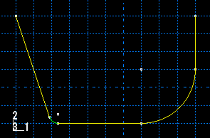
A sketch of an analytical rigid part that includes a line, an arc, and a fillet is illustrated in Figure 11–14.
An analytical rigid part is defined completely by the two-dimensional profile of the base feature that you create with the Sketcher; consequently, the Part module tools cannot be used to add features when you return to the Part module from the Sketcher. You can modify the part only by editing the original sketch.