When your model contains parts that contact each other, you can specify that one or more of the parts is rigid. A rigid part represents a part that is so much stiffer than the rest of the model that its deformation can be considered negligible.
In contrast to a part that you define as rigid, a part that you define as deformable can deform during contact with either a rigid part or another deformable part. For example, a model of a metal stamping process might use a deformable part to model the blank and rigid parts to model the mold and die, as shown in Figure 11–9.
In this example the mold is constrained to have no motion, and the die moves through a prescribed path during the stamping process. You control the motion of rigid parts by selecting a rigid body reference point and constraining or prescribing its motion. For more information, see “The reference point,” Section 11.8.1.Computational efficiency is the principal advantage of rigid parts over deformable parts. During the analysis element-level calculations are not performed for rigid parts. Although some computational effort is required to update the motion of the rigid body and to assemble concentrated and distributed loads, the motion of the rigid body is determined completely by the reference point. To change the type of a part from deformable to rigid and vice versa, you can click mouse button 3 on the part in the Model Tree and select Edit from the menu that appears. For more information, see “What is the difference between a rigid part and a rigid body constraint?,” Section 11.7.3, and “Modeling display bodies,” Section 21.5.
You can choose between two kinds of rigid parts:
Discrete rigid parts
A part that you declared to be a discrete rigid part can be any arbitrary three-dimensional, two-dimensional, or axisymmetric shape. Therefore, you can use all the Part module feature tools—solids, shells, wires, cuts, and blends—to create a discrete rigid part. However, only discrete rigid parts containing shells and wires can be meshed with rigid elements in the Mesh module. If you try to create an instance of a solid discrete rigid part in the Assembly module, ABAQUS/CAE displays an error message; you must return to the Part module and convert the faces of the solid to shells.
Analytical rigid parts
An analytical rigid part is similar to a discrete rigid part in that it is used to represent a rigid part in a contact analysis. If possible, you should use an analytical rigid part when describing a rigid part because it is computationally less expensive than a discrete rigid part. The shape of an analytical rigid part is not arbitrary, and the profile must be smooth. You can use only the following methods to create an analytical rigid part:
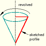
You can sketch the two-dimensional profile of the part and revolve the profile around an axis of symmetry to form a three-dimensional revolved analytical rigid part, as shown in Figure 11–10.
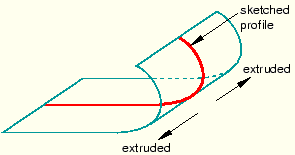
You can sketch the two-dimensional profile of the part and extrude the profile infinitely to form a three-dimensional extruded analytical rigid part. Although ABAQUS/CAE considers that the extrusion extends to infinity, the Part module displays a three-dimensional extruded analytical rigid part with a depth that you specify, as shown in Figure 11–11.
You can sketch the profile of a planar two-dimensional analytical rigid part, as shown in Figure 11–12.
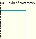
You can sketch the profile of an axisymmetric two-dimensional analytical rigid part, as shown in Figure 11–13.
You can import a part from a file containing geometry stored in a third-party format and define it to be either a deformable or a discrete rigid part; however, you cannot define an imported part to be an analytical rigid part. As an alternative, you can import the geometry of the analytical rigid part into a sketch. You can then create a new analytical rigid part and copy the imported sketch into the Sketcher toolset.
A rigid part in ABAQUS/CAE is equivalent to a rigid surface in an ABAQUS/Standard or ABAQUS/Explicit analysis. For more information, see the following:
“Defining analytical rigid surfaces,” Section 2.3.4 of the ABAQUS Analysis User's Manual
“Defining rigid bodies,” Section 2.4 of the ABAQUS Analysis User's Manual
“Rigid elements,” Section 24.3.1 of the ABAQUS Analysis User's Manual
“Contact interaction analysis: overview,” Section 29.1.1 of the ABAQUS Analysis User's Manual