Products: ABAQUS/Standard ABAQUS/Explicit
The mesh-independent fastener capability:
is a convenient method to define a point-to-point connection between two or more surfaces such as a spot weld or rivet connection;
combines either connector elements or BEAM MPCs with distributing coupling constraints to provide a connection that can be located anywhere between two or more surfaces regardless of the mesh refinement or location of nodes on each surface;
can be used to connect both deformable and rigid element-based surfaces;
can model either rigid, elastic, or inelastic connections with failure by using the generality of connector behavior definitions; and
is available only in three dimensions.
Many applications require modeling of point-to-point connections between parts. These connections may be in the form of spot welds, rivets, screws, bolts, or other types of fastening mechanisms. There may be hundreds or even thousands of these connections in a large system model such as an automobile or airframe.
The fastener can be located anywhere between the parts that are to be connected regardless of the mesh. In other words, the location of the fastener can be independent of the location of the nodes on the surfaces to be connected. Instead, the attachment to each of the parts being connected is distributed to several nodes in the surfaces to be connected in the neighborhood of the attachment points. Figure 28.3.4–1 shows a typical one-layer and two-layer fastener configuration.
Each layer connects two attachment points using either a connector element or a BEAM MPC. Each attachment point is connected to the surface using a distributing coupling constraint that couples the displacement and rotation of each attachment point to the average displacement and rotation of the nearby nodes.The mesh-independent fastener capability in ABAQUS is designed to model these connections in a convenient manner. The fastener automatically:
determines the locations of nodes and orientations of connector elements or BEAM MPCs between two or more surfaces;
generates distributing coupling constraints to attach the connector elements or BEAM MPCs to each surface in a mesh-independent manner; and
calculates weights for the distributing coupling constraints that complete the mesh-independent connection.
Fasteners are defined in groups called interactions. Each fastener interaction is assigned a name, which is used to identify groups of fasteners for output requests and for postprocessing with ABAQUS/CAE.
Each interaction defines one or more fasteners. The number of individual fasteners is equal to the number of reference points used to locate the fasteners. Attachment points on each surface are found by considering the position of the reference point as discussed in subsequent sections.
Fasteners can be defined using connector elements or BEAM MPCs. Beam MPCs allow modeling of perfectly rigid connectors between components; while connector elements allow you to model much more complex behavior, such as deformable connectors that include the effects of elasticity, damage, plasticity, and friction.
| Input File Usage: | *FASTENER, INTERACTION NAME=name |
For modeling perfectly rigid connections you need not define fasteners using connector elements. Instead, ABAQUS can internally generate BEAM MPCs connecting the attachment points of the fasteners. In this approach you assign a reference node set containing a list of user-defined nodes to the fastener interaction. The nodes in this reference node set will be used as reference points to locate the fasteners. If single-layer fasteners are to be modeled, ABAQUS generates single BEAM MPCs with each node in the reference node set becoming the first node of the BEAM MPC. The second node of each BEAM MPC will be generated internally by ABAQUS. If multi-layer fasteners are to be defined, ABAQUS generates linked sets of BEAM MPCs with each node in the reference node set becoming the first node of the first BEAM MPC in each linked set. The subsequent nodes in each linked set will be generated internally by ABAQUS. For multi-layer fasteners each linked set contains as many BEAM MPCs as the number of layers in the fastener.
Using connector elements as the basis for a point-to-point connection allows for very complex behavior to be modeled with fasteners. Like other uses of connector elements, the connection can be fully rigid or may allow for unconstrained relative motion in local connector components. In addition, deformable behavior can be specified using a connector behavior definition that can include the effects of elasticity, damping, plasticity, damage, and friction. There are two methods to define fasteners that use connector elements to model the behavior between attachment points. For both methods the fastener interaction refers to an element set containing the connector elements. You must specify a connector section definition that refers to this element set. You should be careful when specifying the connector orientation (if needed) as discussed below in “Defining the fastener orientation.”
The most controlled approach to specifying fasteners using connector elements is to define the connector elements explicitly and associate them with an element set. The fastener interaction refers to the element set. Each fastener in the fastener interaction corresponds to one or more connector elements depending on the number of layers of the fastener (see Figure 28.3.4–2).
A single connector element is associated with each layer, and the two nodes of the connector element correspond to the attachment points of the two adjacent surfaces. When specifying a multi-layer fastener, the connector elements for each layer should share nodes with the connector elements of adjacent layers.For a single-layer fastener the reference point used to locate the fastener and its attachment points is taken as the nodal coordinates of the first node of the connector element. For a multi-layer fastener the reference point is taken as the first node of the first connector in a linked set of connectors with as many members as layers. Examples of defining a single-layer and multi-layer fastener are included at the end of this section.
| Input File Usage: | Use the following options: |
*FASTENER, INTERACTION NAME=name, ELSET=element set label *ELEMENT, TYPE=CONN3D2, ELSET=element set label *CONNECTOR SECTION, ELSET=element set label |
In this approach you do not need to explicitly define the connector elements that connect the attachment points of the fastener. The fastener interaction refers to an empty element set. You must specify a connector section definition that refers to this element set. In addition, you assign a reference node set containing a list of user-defined nodes to the fastener interaction. The nodes in this reference node set are used as reference points to locate the fasteners.
If single-layer fasteners are to be modeled, ABAQUS generates single connector elements with each node in the reference node set becoming the first node of a connector element. The second node of each connector element will be generated internally by ABAQUS. If multi-layer fasteners are to be defined, ABAQUS generates linked sets of connector elements with each node in the reference node set becoming the first node of the first connector element in each linked set. The subsequent nodes in each linked set will be generated internally by ABAQUS. For multi-layer fasteners each linked set contains as many connector elements as the number of layers in the fastener. The connector elements are given internally generated element numbers and assigned to the named user-specified element set. You can use this element set to request output for these connector elements. However, this element set should not be included in another element set definition.
| Input File Usage: | Use the following options: |
*FASTENER, INTERACTION NAME=name, ELSET=element set label, REFERENCE NODE SET=node set label *NSET, NAME=node set label *CONNECTOR SECTION, ELSET=element set label |
To define a single-layer fastener directly using connector elements:
Define two connector elements with user element numbers 100 and 200 and user-defined node numbers 1, 2 and 3, 4, respectively, and include them in an element set. Nodes 1 and 3 act as the reference points for the two fasteners (see Figure 28.3.4–2).
Refer to the element set in the fastener interaction and connector section definitions.
Assign section properties to the fasteners. Suppose in this example that relative displacements between the attachment points are to be allowed. Therefore, the fasteners must be assigned a section that has available components of motion; for example, a CARTESIAN section can be used.
The relative displacement between the attachment points gives rise to elastic deformations. Hence, the material between the fasteners is modeled as linear elastic with a spring stiffness of 10000 using connector elasticity.
*FASTENER, INTERACTION NAME=fastinter, ELSET=fastconn, PROPERTY=fastprop
surface1, surface2
*ELEMENT, TYPE=CONN3D2, ELSET=fastconn
100, 1, 2
200, 3, 4
*CONNECTOR SECTION, ELSET=fastconn, BEHAVIOR=behav
CARTESIAN,
*CONNECTOR BEHAVIOR, NAME=behav
*CONNECTOR ELASTICITY, COMPONENT=1
10000,
*CONNECTOR ELASTICITY, COMPONENT=2
10000,
*CONNECTOR ELASTICITY, COMPONENT=3
10000,
To define a multi-layer fastener directly using connector elements:
Define two linked sets of connector elements with each linked set containing exactly two connectors. The first linked set comprises element numbers 100 and 101, with node numbers 1, 2 and 2, 3, respectively. The second linked set comprises element numbers 200 and 201, with node numbers 4, 5 and 5, 6, respectively. Include the connector elements in an element set. Nodes 1 and 4 act as the reference points for the two fasteners (see Figure 28.3.4–2).
Refer to the element set in the fastener interaction and connector section definitions
Assign section properties to the fasteners. Suppose in this example that rigid beam-type behavior between the attachment points is to be modeled; in that case the fasteners must be assigned a BEAM section.
*FASTENER, INTERACTION NAME=fastinter, ELSET=fastconn, PROPERTY=fastprop
surface1, surface2
*ELEMENT, TYPE=CONN3D2, ELSET=fastconn
100, 1, 2
101, 2, 3
200, 4, 5
201, 5, 6
*CONNECTOR SECTION, ELSET=fastconn
BEAM,
Each interaction defines one or more fasteners. The number of individual fasteners is equal to the number of reference points used to locate the fasteners. Reference points are nodes defined at the fastener locations and assigned as a node set to the interaction.
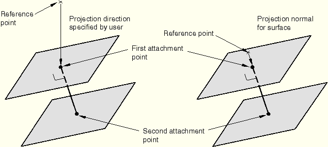
In general, a reference point should be located as close to the surfaces being connected as possible. The reference node specifying the reference point can be one of the nodes on the connected surfaces or can be defined separately. ABAQUS determines the actual points where the fastener layers attach to the surfaces that are being connected by first projecting the reference point onto the closest surface. By default, ABAQUS projects each fastener reference point onto the closest surface along a directed line segment normal to the surface. Alternatively, you can specify the projection direction. Specifying the direction may be useful when two-dimensional drawings are used to identify the reference point locations and those locations are known precisely in two dimensions but not in a third. For this case the direction specified is typically the normal to the plane of the drawing.
Once the attachment point on the closest surface has been identified, ABAQUS determines the points on the other surface or surfaces to be connected by projecting the first attachment point onto the other surfaces along the fastener normal direction, which is typically normal to the closest surface. Figure 28.3.4–3 shows the two ways of locating the projection points.
A user-specified reference point location might not coincide with the locations of the attachment points found by ABAQUS. Hence, the coordinates of the node at the reference point may change from their user-prescribed values when the node is shifted to an attachment point. If the node at the reference point is part of the connectivity of a user-defined element, this can cause the element whose connectivity includes the reference node to undergo unacceptable initial distortions. In such situations it is recommended that you define the reference node separately. In general, you should not specify a reference node to be one of the nodes of the connected surfaces.
| Input File Usage: | Use the following option to allow ABAQUS to define the projection direction: |
*FASTENER, REFERENCE NODE SET=node set label
blank line
Use the following option to define the projection direction directly: *FASTENER, REFERENCE NODE SET=node set label x-component, y-component, z-component |
Once the reference points have been specified, the surfaces to be fastened can be specified using two different approaches. In the first approach you directly specify the surfaces that are to be connected with a fastener. In the second approach you specify a search zone, and ABAQUS automatically identifies the surfaces that are to be connected. However, in the second approach ABAQUS does not distinguish between coincident facets. Hence, if coincident facets are to be fastened, you should specify distinct surfaces containing each of the coincident facets and use the first approach. Only element-based surfaces defined on faces can be fastened together (see “Defining element-based surfaces,” Section 2.3.2, and “Operating on surfaces,” Section 2.3.5).
If you specify multiple surfaces as part of the interaction definition, the surfaces to be fastened are restricted to these surfaces. The number of layers of each fastener is one less than the number of surfaces specified. One attachment point is found on each surface.
| Input File Usage: | *FASTENER first data line surface1, surface2, surface3, etc. |
By default, the connectivity of the attachment points is determined by their relative position along the fastener projection direction. For example, the default connectivity for the two-layer example shown in Figure 28.3.4–1 connects attachment point A to point B (layer 1) and point B to point C (layer 2). For fasteners defined using BEAM MPCs the connectivity is important for output, which is calculated in the fastener layers.
You can control the connectivity of the attachment points when the fasteners are formed on user-specified surfaces. You can specify that the connectivity of the attachment points be defined by the order in which you specified their associated surfaces.
| Input File Usage: | *FASTENER, UNSORTED first data line surface1, surface2, surface3, etc. |
If user-specified surfaces are not included on the data lines, the UNSORTED parameter is ignored. |
If you do not specify any surfaces as part of the interaction definition, ABAQUS searches for attachment points on all shell and rigid element facets that fall within a sphere of user-specified radius R with its center at the fastener reference point. If you do not specify the search radius, ABAQUS computes a default search radius based on five times the facet thickness (for shell element facets) or the characteristic element length (for rigid element facets) in the vicinity of each fastener reference point.
To refine the search, you can specify a single surface definition that will limit the facet search to element facets belonging to that surface. In this case you must define a collective surface that includes at least each connected surface. A combined surface can also be used (see “Operating on surfaces,” Section 2.3.5, for a discussion on combining surfaces).
To refine the search further, you can specify a positive integer value, N, for the number of layers of each fastener. ABAQUS searches for the ![]() attachment points closest to the reference point. If BEAM MPCs are used to model the fastener, a warning message is issued if the requisite number of attachment points is not found. However, if connector elements are used to model the fastener and the requisite number of attachment points is not found, ABAQUS issues an error message. Thus, when specifying the number of layers, you should ensure that the search radius has been specified such that
attachment points closest to the reference point. If BEAM MPCs are used to model the fastener, a warning message is issued if the requisite number of attachment points is not found. However, if connector elements are used to model the fastener and the requisite number of attachment points is not found, ABAQUS issues an error message. Thus, when specifying the number of layers, you should ensure that the search radius has been specified such that ![]() attachment points can be found.
attachment points can be found.
If multiple surfaces are listed as part of the fastener definition, the number of layers for each fastener are ignored. If a user-specified search radius is used for the multiple surface case,ABAQUS searches for attachment points on all facets belonging to each of the listed surfaces that fall within a sphere of user-specified radius R with its center at the fastener reference point. Facets of the listed multiple surfaces that lie outside this sphere are not included in the search.
| Input File Usage: | *FASTENER, SEARCH RADIUS=R, NUMBER OF LAYERS=N first data line |
Each fastener attachment point is associated with a group of nodes on the surface in the immediate neighborhood of the attachment point called a region of influence. The motion of the attachment point is then coupled in a weighted sense to the motion of the nodes in this region by a distributed coupling constraint. Several weighting options are available and are discussed in the next section.
To define the region of influence, ABAQUS computes a default radius of influence based on the geometric properties of the fastener, the characteristic length of the connected facets, and the type of weighting function used. The radius of influence is always chosen to be as large as or larger than the physical fastener radius. You can override the default calculation by specifying the desired radius of influence. In any case each region of influence will contain a minimum of three nodes.
| Input File Usage: | *FASTENER, RADIUS OF INFLUENCE=distance |
The weighting methods available for the distributed coupling constraints created for a fastener interaction are the same as those available for the surface-based coupling constraints in ABAQUS (see “Coupling constraints,” Section 28.3.2). Besides an area-based uniform weighting scheme, various weighting methods are provided that monotonically decrease with radial distance from the attachment point: linear, quadratic, and cubic polynomial weight distributions. By default, ABAQUS uses the uniform weighting method. You can modify the default weighting distribution.
The default radius of influence calculated by ABAQUS is larger for higher-order weighting methods since the resulting weights for nodes away from the fastener attachment point contribute comparatively little to the motion of the attachment point. Hence, to ensure that there is a sufficient “smearing” effect, it becomes necessary to increase the number of nodes in the region of influence by increasing the size of the default radius of influence. In comparison, for a uniform weighting scheme, surface nodes away from the fastener attachment point contribute significantly to the motion of the attachment point. For this case the default radius of influence chosen can be comparatively small, since even with a small number of nodes in the region of influence, the smearing effect is sufficiently strong.
| Input File Usage: | Use the following option to specify a uniform weight distribution: |
*FASTENER, WEIGHTING METHOD=UNIFORM Use the following option to specify a linear weight distribution: *FASTENER, WEIGHTING METHOD=LINEAR Use the following option to specify a quadratic polynomial weight distribution: *FASTENER, WEIGHTING METHOD=QUADRATIC Use the following option to specify a cubic polynomial weight distribution: *FASTENER, WEIGHTING METHOD=CUBIC |
Each fastener is formulated in a local coordinate system that rotates with the motion of the fastener. By default, ABAQUS defines the local system by projecting the global coordinate system onto the surfaces that are being fastened according to the usual convention for surfaces in space (see “Conventions,” Section 1.2.2). Local directions specified in this manner are such that the local z-axis for each fastener is normal to the surface that is closest to the reference node for the fastener.
You can override the default local system by specifying a local coordinate system for the fastener interaction. Generally, the user-defined orientation should be such that the local z-axis of the orientation is approximately normal to the surfaces that are being connected and the local x- and y-axes are approximately tangent to the surfaces that are being connected. By default, ABAQUS adjusts the user-defined orientation such that the local z-axis for each fastener is normal to the surface that is closest to the reference node for the fastener. In cases where you wish to define the local directions precisely, you can specify that ABAQUS should not adjust them.
In geometrically nonlinear analysis steps the local directions rotate with the motion of the fastener reference node.
If a connector element is used to model a fastener, the local coordinate system defined on the connector section (![]() ) operates on the local coordinate system for the fastener (
) operates on the local coordinate system for the fastener (![]() ) to determine the final local coordinate system of the connector element (
) to determine the final local coordinate system of the connector element (![]() ). In other words,
). In other words,
![]()
For example, suppose you use a HINGE connector and want the released rotational degree of freedom, which is in the connector's local 1-direction, to be normal to the surfaces that are being fastenened. If the default local coordinate system is used for the fastener (local 3-direction normal to the surface), the local 1-direction for the connector should be set to (0., 0., 1.); i.e., the local 3-direction of the fastener. When compounded with the local coordinate system for the fastener, the local 1-direction for the connector will be normal to the surface. See “Mesh-independent spot welds,” Section 5.1.14 of the ABAQUS Verification Manual, for an example of a compounded orientation.
| Input File Usage: | *FASTENER, ORIENTATION=orientation name, ADJUST ORIENTATION=NO |
There are two methods available to couple the motion of each attachment point to the motion of the associated coupling nodes on the fastened surfaces: the continuum coupling method and the structural coupling method. The continuum coupling method is used by default.
In many cases when the pair of fastened surfaces are close to each other, unrealistic contact interactions may occur between the two surfaces if the continuum coupling method is used. This is particularly the case in shell bending applications. Moreover, in many situations the continuum coupling method can yield an overly stiff response if the two surfaces are pried apart, especially when the fastener radius is small. The structural coupling method can be used to alleviate these issues.
The default continuum coupling method couples the translation and rotation of each attachment point to the average translation of the group of coupling nodes on each of the fastened surfaces. The constraint distributes the forces and moments at the attachment point as a coupling node-force distribution only. The force distribution is equivalent to the classic bolt pattern force distribution when the weight factors are interpreted as bolt cross-section areas. For each pair of attachment point and group of coupling nodes, the constraint enforces a rigid beam connection between the attachment point and a point located at the weighted center of position of the coupling nodes. The formulation is discussed in detail in “Distributing coupling elements,” Section 3.9.8 of the ABAQUS Theory Manual.
| Input File Usage: | *FASTENER, COUPLING=CONTINUUM |
The structural coupling method couples the translation and rotation of each attachment point to the translation and the rotation motion of the group of coupling nodes on each of the fastened surfaces. The constraint distributes forces and moments at the attachment point as coupling nodes forces and moments. For this coupling method to be active, all rotation degrees of freedom at all coupling nodes must be active (as would be the case when shells are fastened together) and all degrees of freedom must be constrained (which is the default; see “Defining fastener properties” below).
With respect to translations, for each pair of attachment point-group of coupling nodes, the constraint enforces a rigid beam connection between the attachment point and a moving point that remains at all times in the vicinity of the fastened surface. The location of this moving point is determined by the current curvature of the surface, the current location of the weighted center of position of the coupling nodes, and the fastener projection direction. This choice avoids unrealistic contact interactions between the fastened surfaces when the surfaces are close to each other (typically the case).
With respect to rotations, for each pair of attachment point-group of coupling nodes, the constraint is different along different local directions. Along the projection direction (the twist direction) , the constraint is identical to the one enforced via the continuum coupling method (see “Distributing coupling elements,” Section 3.9.8 of the ABAQUS Theory Manual). By contrast, the rotational constraint in the plane perpendicular to the projection direction relates the in-plane attachment point rotations to the in-plane rotations of the coupling nodes in the immediate vicinity of the attachment point. This choice provides a more realistic response when the fastened surfaces are pried apart.
| Input File Usage: | *FASTENER, COUPLING=STRUCTURAL |
Each fastener interaction definition must refer to a property, which defines the geometric section properties of the fastener.
| Input File Usage: | Use both of the following options: |
*FASTENER, PROPERTY=fastener property name *FASTENER PROPERTY, NAME=fastener property name |
Fasteners are assumed to have a circular projection onto the connected surfaces. You are required to specify the radius of the fastener.
In many cases fasteners may add mass to the assembly. To model the added mass, specify an additional mass that is assigned to each fastener and lumped to the attachment points.
| Input File Usage: | *FASTENER PROPERTY, MASS=mass value |
For fasteners modeled with connector elements, translational as well as rotational degrees of freedom can be released by prescribing connector section types that have unconstrained (available) degrees of freedom. For example, a HINGE connector can be used to release the rotational degree of freedom in the connector's local 1-direction.
For fasteners modeled with BEAM MPCs, the moment constraint between the rotation degrees of freedom at the attachment points and the average rotation of the coupling nodes can be released in one, two, or three directions. You can specify the moment constraint directions in the default local coordinate system or a user-defined local coordinate system. The three translational degrees of freedom at the attachment points are always coupled to the average translation of the coupling nodes. You specify the degrees of freedom of the attachment point to be coupled to the average motion of the coupling nodes as part of the fastener property definition.
If no degrees of freedom are specified as part of the fastener property definition, all six degrees of freedom are coupled. If you specify one or more degrees of freedom but not all available translation degrees of freedom, ABAQUS issues a warning message and adds all the available translation degrees of freedom to the constraint. If a user-specified local orientation is specified for the fastener interaction, the local degrees of freedom are with respect to the user-defined coordinate system.
| Input File Usage: | *FASTENER PROPERTY section properties first dof, last dof |
For example, if the default local coordinate system is used, the following property definition would release the relative rotation constraint of the connected parts about the surface normal: *FASTENER PROPERTY section properties 1, 5 The above property definition might be used to approximate a riveted connection. |
There are several instances in which a model with fasteners modeled with BEAM MPCs might be overconstrained. Described below are two potential overconstraints that ABAQUS automatically attempts to detect and resolve during solver input file processing.
Fasteners can be used to connect both deformable and rigid element-based surfaces. However, if the fasteners are modeled with BEAM MPCs, potential overconstraints may arise if more than one rigid surface is involved in a given fastener definition. ABAQUS automatically attempts to remove these types of overconstraints by allowing at most one rigid surface in any individual fastener definition. A warning message is generated if an overconstraint of this type is detected.
For example, suppose surfaces A and C in Figure 28.3.4–1 are rigid, and surface B is deformable. ABAQUS automatically removes either surface A or surface C from the fastener definition and only forms the fastener between the deformable surface and the remaining rigid surface. If surface A and surface C belong to two separate rigid bodies, their respective rigid body reference nodes will be joined by an internally generated BEAM MPC.
In another example, suppose all three surfaces in Figure 28.3.4–1 are rigid. In this case no fastener will be formed, and the unique rigid body reference nodes for surfaces A, B, and C will be joined by beam MPCs. Unresolvable overconstraints may arise if inconsistent kinematic constraints (such as displacement boundary conditions) are placed on rigid body reference nodes that have been joined by BEAM MPCs. In this case you must modify the model to resolve the overconstraints. Possible courses of action include removing some of the rigid surfaces from the fastener definitions or removing inconsistent kinematic conditions on the rigid body reference nodes.
The above-described procedure to resolve overconstraints with fasteners and rigid bodies will preserve the kinematics of the original model. However, the internal forces in the associated fasteners are not available for output (see the discussion of fastener output below).
In ABAQUS/Standard you can bypass the overconstraint checks and prevent automatic model modifications in the model preprocessor (see “Overconstraint checks,” Section 28.6.1).
Potential overconstraints exist with rigid fasteners if all the coupling nodes of any associated distributing coupling element are wholly contained within one or more other fastener definitions. This can happen if the spacing between fastener reference points is small compared to the typical element size in a mesh (which is often the case in automotive models). To avoid overconstraints in this situation, ABAQUS uses a penalty formulation for all fastener distributing coupling elements that satisfy the above criteria. The penalty distributing coupling formulation relaxes, to a small degree, the constraint between the motion of the distributing coupling element reference node and its coupling nodes.
The output from fasteners depend on whether connector elements or BEAM MPCs are used to model the fastener.
If fasteners are modeled using connector elements, connector element output variables can be used to request output for fasteners (see “Connector elements,” Section 25.1.2). No fastener-specific output variables exist for such fasteners.
If the fasteners are modeled as BEAM MPCs, the only quantities that are available for output are the forces and moments carried by each fastener layer (output variable FTF). Output associated with these fastener interactions can be written to the output database (.odb) file and to the ABAQUS/Standard data (.dat) file. The fastener forces and moments for each layer are computed at the midpoint between the associated surfaces. Output variable FTF can be written only as history output to the output database and can be viewed in X–Y plots in ABAQUS/CAE.
You can request output for all fasteners in the model, all fasteners associated with a given interaction name, or all fasteners associated with a set of fastener reference nodes. Detailed discussions of requesting fastener interaction output can be found in “Output to the data and results files,” Section 4.1.2, and “Output to the output database,” Section 4.1.3.
Output is not available for any fastener that is used to connect two or more surfaces if any of the surfaces connected is a rigid surface.
The following fastener force and moment components are available for output:
FTF1 | Force in the local 1-direction. |
FTF2 | Force in the local 2-direction. |
FTF3 | Force in the local 3-direction. |
FTM1 | Moment about the local 1-direction. |
FTM2 | Moment about the local 2-direction. |
FTM3 | Moment about the local 3-direction. |
| Input File Usage: | Use either of the following options: |
*INTERACTION OUTPUT *INTERACTION PRINT |