Products: ABAQUS/Standard ABAQUS/Explicit ABAQUS/CAE
Connector elements:
are available for two-dimensional, axisymmetric, and three-dimensional analyses;
can define a connection between two nodes (each node can be connected to a rigid part, a deformable part, or not connected to any part);
can define a connection between a node and ground;
have relative displacements and rotations that are local to the element, which are referred to as components of relative motion;
are functionally defined by specifying the connector attributes;
have comprehensive kinematic and kinetic output; and
can be used to monitor kinematics in local coordinate systems.
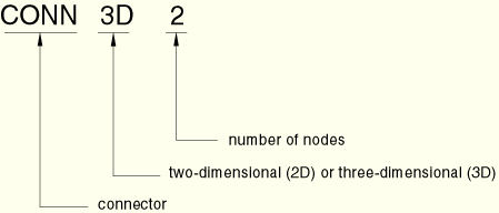
Two connector elements are provided. The element type to be chosen depends on the dimensionality of the analysis: CONN2D2 for two-dimensional and axisymmetric analyses and CONN3D2 for three-dimensional analyses. Both connector elements have at most two nodes. The position and motion of the second node on the connector element are measured relative to the first node.
Connector elements in ABAQUS are named as follows:
A connector element can be used to connect two points.
| Input File Usage: | *ELEMENT, TYPE=name connector element number, node_1, node_2 |
| ABAQUS/CAE Usage: | Interaction module: Connector |
A connector element can be connected to ground, and the ground “node” can be the first or second point on the connector element. The initial position of the ground node used for calculating relative position and displacement is the initial position of the other point on the element. All displacements and rotations at the ground node, if they exist, are fixed.
| ABAQUS/CAE Usage: | Interaction module: Connector |
Connector elements have relative displacements and rotations that are local to the element. These relative displacements and rotations are referred to as components of relative motion. In the three-dimensional case connector elements use 12 nodal degrees of freedom to define six relative motion components: three displacements and three rotations in element local directions. In two dimensions six nodal degrees of freedom define three relative motion components: two displacements and one rotation. The components of relative motion are either constrained or unconstrained (“available”), depending upon the definition of the connector element.
Constrained components of relative motion are displacements and rotations that are fixed by the connector element.
In connector elements with constrained components of relative motion, ABAQUS uses Lagrange multipliers to enforce the kinematic constraints. Accordingly, in ABAQUS/Standard the constraint forces and moments carried by the element appear as additional solution variables. The number of additional solution variables is equal to the number of constrained components of relative motion.
Available components of relative motion are displacements and rotations that are not constrained kinematically and, hence, remain available for defining material-like behavior, specifying time-dependent motion, applying loading, or assigning complex interactions, such as contact or friction. Many connection types have available components of relative motion, and their meaning is described in “Connection-type library,” Section 25.1.5, for each individual connection type.
The connection attributes define the connector element's function. In the most general case you specify the following attributes:
the connection type or types,
the local directions associated with the connector's nodes, and
the connector behavior.
| Input File Usage: | *CONNECTOR SECTION, ELSET=name |
| ABAQUS/CAE Usage: | Interaction module: |
ABAQUS provides a comprehensive library of connection types. See “Connection-type library,” Section 25.1.5, for the available connection types. The connection types are divided into two categories: basic connection components and assembled connections. The basic connection components affect either translations or rotations on the second node. A connector element may include one translational basic connection component and/or one rotational basic connection component. The assembled connections are constructed from the basic connection components. They are provided for convenience and cannot be combined in the same connector element definition with a basic connection component or other assembled connections.
The connection type is specified as:
a single basic connection type (translational or rotational),
one translational and one rotational basic connection type, or
one assembled connection type.
| Input File Usage: | Use one of the following options: |
*CONNECTOR SECTION, ELSET=name basic connection type, basic connection type *CONNECTOR SECTION, ELSET=name assembled connection |
| ABAQUS/CAE Usage: | Interaction module: |
Local directions at the nodes are often required to define the connection types used to define the connector element. The local directions and how they are used to define the connection are described in “Connection-type library,” Section 25.1.5. In the most general case the connection type uses two sets of local directions, which are defined as described in “Orientations,” Section 2.2.5. The names associated with the two orientation definitions must be referred to from the connector section definition.
| Input File Usage: | Use the following options for the most general case: |
*ORIENTATION, NAME=orientation_1 *ORIENTATION, NAME=orientation_2 *CONNECTOR SECTION, ELSET=name basic connection type(s) or assembled connection orientation_1 for first node (or ground), orientation_2 for second node (or ground) |
| ABAQUS/CAE Usage: | Interaction module: Connector |
Many connection types either require connection directions at the nodes on the element or allow optional directions to be defined. In cases where an orientation definition is permitted for defining connection directions (required or optional), connector elements activate the rotational degrees of freedom at the nodes to which they are attached, if they do not exist already. The only exception is connection type JOIN, for which connection directions are optional at the first node of the element, but rotation degrees of freedom are not activated.
The connector element's orientation directions co-rotate with the rotational degrees of freedom at the corresponding node on the element. If there is no element with rotational degrees of freedom or rotation constraint (such as an equation or a multi-point constraint) attached to the node, you must ensure that sufficient rotational boundary conditions are provided to avoid numerical singularities associated with unconstrained rotational degrees of freedom. Connection type JOIN uses fixed directions when rotational degrees of freedom are not active at the nodes on the connector element.
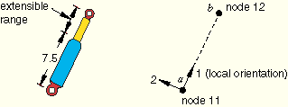
Figure 25.1.2–1 illustrates the use of the CONN3D2 element to connect two bodies with a cylindrical-like connector oriented at 60° from the global 1-axis. On the left is a schematic representation of the connection to be modeled; on the right is a representation of the equivalent finite element model. See “Connection-type library,” Section 25.1.5, for a list of connector type names.
The connection requires node b to remain on the line of the shock absorber, which is determined by the position and orientation directions of node a. Furthermore, the two rotation components perpendicular to the line of the shock absorber at node b must be the same as those at node a. Hence, the only relative motion components permitted in the connection are the displacement of node b relative to node a along the line of the shock absorber and the rotation of node b relative to node a about the line of the shock absorber. This displacement and this rotation are the available components of relative motion. The connector is defined using the following lines in the input file:
*ELEMENT, TYPE=CONN3D2, ELSET=shock
101, 11, 12
*CONNECTOR SECTION, ELSET=shock
slot, revolute
ori60,
*ORIENTATION, NAME=ori60
**Defines the local 1-direction along the slot (required)
**Also defines the rotation axis for the revolute (required)
0.5, 0.866025, 0.0, -0.866025, 0.5, 0.0
Alternatively, you could use the assembled connection type CYLINDRICAL instead of the two basic connection types SLOT and REVOLUTE.
ABAQUS provides comprehensive kinetic behavior modeling in the available components of relative motion. Defining connector behavior is optional and can be used to incorporate spring, dashpot, node-to-node contact, locking, friction, plasticity-like effects, and failure. The kinetic modeling capabilities in connectors are described in detail in “Connector behavior,” Section 25.2.1.
Not all connection types can be used with element type CONN2D2. The connection-type library contains many connection types whose mechanics are valid for three-dimensional analyses only. In other cases the local directions required in the definition of the connection type conflict with the two-dimensional coordinate system. See “Connection-type library,” Section 25.1.5, for more information.
Connector elements in ABAQUS allow most physical connections to be modeled with a single connector element. However, in certain circumstances more complex connections or output considerations may require multiple connector elements to be used in parallel. This is accomplished by defining two or more connector elements between the same nodes. In this case you must ensure that a constrained component of relative motion in one connector element is not constrained (either by a kinematic constraint or through motion specified as described in “Connector actuation,” Section 25.1.3) by one of the other connector elements.
Multiple connector elements are sometimes used in parallel to obtain output in different coordinate systems. For a connector element between two bodies, the local directions at the nodes can be determined by the requirements of the connection type. However, output may be needed in a different, possibly co-rotating, coordinate system. For example, the angular acceleration history could be reported in a local, body-fixed coordinate system (other than the one used to define the connector element) by using a second connector element (such as connection type CARDAN) that does not impose kinematic constraints or use connector behavior but aligns with the desired local output directions.
An ABAQUS model can be defined in terms of an assembly of part instances (see “Defining an assembly,” Section 2.9.1). Connector elements can be defined at either the part level or the assembly level in such a model.
Nodal transformations (see “Transformed coordinate systems,” Section 2.1.5) can be defined for either node connected to the connector element. Since these transformations affect only the nodal degrees of freedom, their use does not affect the behavior of the connector element. Connector elements operate on components of motion local to the connection.
If a connector element with a nonlinear kinematic constraint is used in a geometrically linear analysis, the kinematic constraint is linearized. For example, if connection type LINK is used in a geometrically linear analysis, the distance between the two nodes is held constant after projection onto the direction of the line between the original positions of the nodes. The difference should be noticeable only if the magnitudes of the rotations and displacements are not small.
If the nodes of a connector element in ABAQUS/Explicit have masses that are highly mismatched, the implicit solver may encounter convergence problems due to the resulting ill-conditioned coefficient matrix. To prevent this from happening, if the nodal masses or rotary inertias of a connector element differ by more than three orders of magnitude, ABAQUS/Explicit adds mass/rotary inertia to the connector element node that has the smaller mass/rotary inertia. The mass/rotary inertia added is negligibly small (less than three orders of magnitude smaller) compared to the larger of the connector element's nodal inertias. This additional mass almost never affects the solution significantly. However, in certain situations (for example, for a strongly dynamic analysis that has connector elements with highly mismatched nodal masses) this adjustment may have a noticeable effect.
The connector element force, moment, and kinematic output is defined in “Connector element library,” Section 25.1.4. These output quantities include total, elastic, viscous, and friction forces and moments. In addition, reaction forces and moments caused by connector stops and locks are available as well as connector contact forces used for friction calculation.
To obtain accurate reaction force and moment output for connectors from ABAQUS/Explicit, it may sometimes be necessary to run the analysis in double precision. In such situations a double precision run will also yield a better estimate of the work done by the reaction forces and moments, thereby providing a more accurate value of the energy due to the external work reported by ABAQUS/Explicit.
Kinematic output includes relative position, relative displacement, relative velocity, relative acceleration, frictional slip, and constitutive displacements (the displacement used in the elastic force and hysteretic friction calculations defined as the difference between the current relative positions and the reference positions; see “Defining reference lengths and angles for constitutive response” in “Connector behavior,” Section 25.2.1). For relative rotations the ABAQUS convention of reporting angles between ![]() and
and ![]() radians is not used with connector elements. Connector element output of angles and rotational components or relative motion includes accumulated multiple rotations whose magnitudes can be arbitrarily large. Energy output is available, as are output flags to identify whether a connector has failed (in ABAQUS/Explicit only), locked, or reached a connector stop.
radians is not used with connector elements. Connector element output of angles and rotational components or relative motion includes accumulated multiple rotations whose magnitudes can be arbitrarily large. Energy output is available, as are output flags to identify whether a connector has failed (in ABAQUS/Explicit only), locked, or reached a connector stop.
In a geometrically linear step in ABAQUS/Standard the relative position output variable does not change (in the same fashion that the nodal coordinates are output). Therefore, care must be exercised in interpreting output for connector stops and locks since they use updated coordinates.
Connector elements defined without kinematic constraints or constitutive behavior can be used to monitor kinematic output in local coordinate systems. Quantities of interest include relative position, displacement, velocity, and acceleration in local coordinate parametrization. Finite rotation parametrizations include Euler and Cardan angles, rotation vector, and flexion-torsion-sweep. For an example that uses a connector element to monitor Euler angles, see “Motion of a rigid body in ABAQUS/Standard,” Section 1.3.6 of the ABAQUS Benchmarks Manual.