Product: ABAQUS/Standard
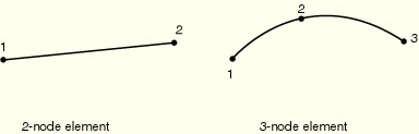
| ELBOW31 | 2-node pipe in space with deforming section, linear interpolation along the pipe |
| ELBOW32 | 3-node pipe in space with deforming section, quadratic interpolation along the pipe |
| ELBOW31B | 2-node pipe in space with ovalization only, axial gradients of ovalization neglected |
| ELBOW31C | 2-node pipe in space with ovalization only, axial gradients of ovalization neglected. This formulation is the same as that for element type ELBOW31B, with the exception that all odd numbered terms in the Fourier interpolation around the pipe but the first term are neglected. |
Distributed loads are specified as described in “Distributed loads,” Section 27.4.3.
Load ID (*DLOAD): BX
Units: FL–3
Description: Body force per unit volume in global X-direction.
Load ID (*DLOAD): BY
Units: FL–3
Description: Body force per unit volume in global Y-direction.
Load ID (*DLOAD): BZ
Units: FL–3
Description: Body force per unit volume in global Z-direction.
Load ID (*DLOAD): BXNU
Units: FL–3
Description: Nonuniform body force in global X-direction with magnitude supplied via user subroutine DLOAD.
Load ID (*DLOAD): BYNU
Units: FL–3
Description: Nonuniform body force in global Y-direction with magnitude supplied via user subroutine DLOAD.
Load ID (*DLOAD): BZNU
Units: FL–3
Description: Nonuniform body force in global Z-direction with magnitude supplied via user subroutine DLOAD.
Load ID (*DLOAD): CENT
Units: FL–4(ML–3T–2)
Description: Centrifugal load (magnitude is input as ![]() , where
, where ![]() is the mass density per unit volume and
is the mass density per unit volume and ![]() is the angular velocity).
is the angular velocity).
Load ID (*DLOAD): CENTRIF
Units: T–2
Description: Centrifugal load (magnitude is input as ![]() , where
, where ![]() is the angular velocity).
is the angular velocity).
Load ID (*DLOAD): GRAV
Units: LT–2
Description: Gravity loading in a specified direction (magnitude is input as acceleration).
Load ID (*DLOAD): HPE
Units: FL–2
Description: Hydrostatic external pressure, with linear variation in global Z (closed-end condition).
Load ID (*DLOAD): HPI
Units: FL–2
Description: Hydrostatic internal pressure, with linear variation in global Z (closed-end condition).
Load ID (*DLOAD): PE
Units: FL–2
Description: Uniform external pressure (closed-end condition).
Load ID (*DLOAD): PI
Units: FL–2
Description: Uniform internal pressure (closed-end condition).
Load ID (*DLOAD): PENU
Units: FL–2
Description: Nonuniform external pressure with magnitude supplied via user subroutine DLOAD (closed-end condition).
Load ID (*DLOAD): PINU
Units: FL–2
Description: Nonuniform internal pressure with magnitude supplied via user subroutine DLOAD (closed-end condition).
Load ID (*DLOAD): ROTA
Units: T–2
Description: Rotary acceleration load (magnitude is input as ![]() , where
, where ![]() is the rotary acceleration).
is the rotary acceleration).
ABAQUS/Aqua loads are specified as described in “ABAQUS/Aqua analysis,” Section 6.10.1.
Load ID (*CLOAD/ *DLOAD): FDD
Units: FL–1
Description: Transverse fluid drag load.
Load ID (*CLOAD/ *DLOAD): FD1
Units: F
Description: Fluid drag force on the first end of the elbow (node 1).
Load ID (*CLOAD/ *DLOAD): FD2
Units: F
Description: Fluid drag force on the second end of the elbow (node 2 or node 3).
Load ID (*CLOAD/ *DLOAD): FDT
Units: FL–1
Description: Tangential fluid drag load.
Load ID (*CLOAD/ *DLOAD): FI
Units: FL–1
Description: Transverse fluid inertia load.
Load ID (*CLOAD/ *DLOAD): FI1
Units: F
Description: Fluid inertia force on the first end of the elbow (node 1).
Load ID (*CLOAD/ *DLOAD): FI2
ABAQUS/CAE Load/Interaction:
Units: F
Description: Fluid inertia force on the second end of the elbow (node 2 or node 3).
Load ID (*CLOAD/ *DLOAD): PB
Units: FL–1
Description: Buoyancy force (closed-end condition).
Load ID (*CLOAD/ *DLOAD): WDD
Units: FL–1
Description: Transverse wind drag load.
Load ID (*CLOAD/ *DLOAD): WD1
Units: F
Description: Wind drag force on the first end of the elbow (node 1).
Load ID (*CLOAD/ *DLOAD): WD2
Units: F
Description: Wind drag force on the second end of the elbow (node 2 or node 3).
The default stress output points are on the inside surface and the outside surface at all integration stations around the pipe.
Stress and other tensors (including strain tensors) are available for elements with displacement degrees of freedom. All tensors have the same components. For example, the stress components are as follows:
S11 | Direct stress along the pipe. |
S22 | Direct stress around the pipe section. |
S12 | Shear stress in the pipe wall. |
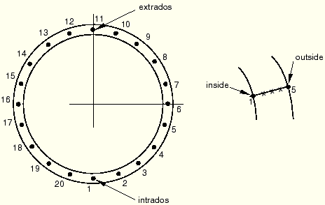
The extrados is the side of the pipebend that is furthest away from the center of the torus defining the pipebend; that is, the side of the pipebend to which the ![]() -axis points. The intrados is the side of the pipebend closest to the center of the torus.
-axis points. The intrados is the side of the pipebend closest to the center of the torus.
The middle surface integration points around a section are shown above. There is a default of five thickness direction integration points at each such point, with point 1 on the inside surface of the pipe and point 5 on the outside surface.
For ELBOW31 and ELBOW31B only one integration station is used along the axis of the element. For ELBOW32 two integration stations are used along the axis of the elbow and the point numbers on the second section are a continuation of those on the first section (e.g., 21, 22, …, 40 in the default case), located around the pipe as shown above.