Product: ABAQUS/Standard
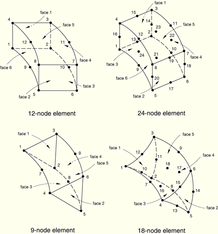
| CCL9 | 9-node cylindrical prism, linear interpolation in the radial plane and trigonometric interpolation along the circumferential direction |
| CCL9H | 9-node cylindrical prism, linear interpolation in the radial plane and trigonometric interpolation along the circumferential direction, hybrid with constant pressure in plane and linear pressure in the circumferential direction |
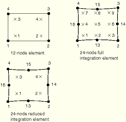
| CCL12 | 12-node cylindrical brick, linear interpolation in the radial plane and trigonometric interpolation along the circumferential direction |
| CCL12H | 12-node cylindrical brick, linear interpolation in the radial plane and trigonometric interpolation along the circumferential direction, hybrid with constant pressure in plane and linear pressure in circumferential direction |
| CCL18 | 18-node cylindrical prism, quadratic interpolation in the radial plane and trigonometric interpolation along the circumferential direction |
| CCL18H | 18-node cylindrical prism, quadratic interpolation in the radial plane and trigonometric interpolation along the circumferential direction, hybrid with linear pressure in plane and linear pressure in the circumferential direction |
| CCL24 | 24-node cylindrical brick, quadratic interpolation in the radial plane and trigonometric interpolation along the circumferential direction |
| CCL24H | 24-node cylindrical brick, quadratic interpolation in the radial plane and trigonometric interpolation along the circumferential direction, hybrid with linear pressure in plane and linear pressure in circumferential direction |
| CCL24R | 24-node cylindrical brick, reduced integration, quadratic interpolation in the radial plane and trigonometric interpolation along the circumferential direction |
| CCL24RH | 24-node cylindrical brick, reduced integration, quadratic interpolation in the radial plane and trigonometric interpolation along the circumferential direction, hybrid with linear pressure in plane and linear pressure in circumferential direction |
Distributed loads are specified as described in “Distributed loads,” Section 27.4.3.
Load ID (*DLOAD): BX
Units: FL–3
Description: Body force in global X-direction.
Load ID (*DLOAD): BY
Units: FL–3
Description: Body force in global Y-direction.
Load ID (*DLOAD): BZ
Units: FL–3
Description: Body force in global Z-direction.
Load ID (*DLOAD): BXNU
Units: FL–3
Description: Nonuniform body force in global X-direction with magnitude supplied via user subroutine DLOAD.
Load ID (*DLOAD): BYNU
Units: FL–3
Description: Nonuniform body force in global Y-direction with magnitude supplied via user subroutine DLOAD.
Load ID (*DLOAD): BZNU
Units: FL–3
Description: Nonuniform body force in global Z-direction with magnitude supplied via user subroutine DLOAD.
Load ID (*DLOAD): CENT
Units: FL–4(ML–3T–2)
Description: Centrifugal load (magnitude is input as ![]() , where
, where ![]() is the mass density per unit volume,
is the mass density per unit volume, ![]() is the angular velocity).
is the angular velocity).
Load ID (*DLOAD): CENTRIF
Units: FL–4(ML–3T–1)
Description: Centrifugal load (magnitude is input as ![]() , where
, where ![]() is the angular velocity).
is the angular velocity).
Load ID (*DLOAD): CORIO
Units: FL–4T (ML–3T–1)
Description: Coriolis force (magnitude is input as ![]() , where
, where ![]() is the mass density per unit volume,
is the mass density per unit volume, ![]() is the angular velocity).
is the angular velocity).
Load ID (*DLOAD): GRAV
Units: LT–2
Description: Gravity loading in a specified direction (magnitude is input as acceleration).
Load ID (*DLOAD): HPn
Units: FL–2
Description: Hydrostatic pressure on face n, linear in global Z.
Load ID (*DLOAD): Pn
Units: FL–2
Description: Pressure on face n.
Load ID (*DLOAD): ROTA
Units: T–2
Description: Rotary acceleration load (magnitude is input as ![]() , where
, where ![]() is the rotary acceleration).
is the rotary acceleration).
Load ID (*DLOAD): TRSHRn
Units: FL–2
Description: Shear traction on face n.
Load ID (*DLOAD): TRSHRnNU(S)
Units: FL–2
Description: Nonuniform shear traction on face n with magnitude and direction supplied via user subroutine UTRACLOAD.
Load ID (*DLOAD): TRVECn
Units: FL–2
Description: General traction on face n.
Load ID (*DLOAD): TRVECnNU(S)
Units: FL–2
Description: Nonuniform general traction on face n with magnitude and direction supplied via user subroutine UTRACLOAD.
Foundations are available for all cylindrical elements. They are specified as described in “Element foundations,” Section 2.2.2.
Load ID (*FOUNDATION): Fn
Units: FL–3
Description: Elastic foundation on face n.
Surface-based distributed loads are available for elements with displacement degrees of freedom. They are specified as described in “Distributed loads,” Section 27.4.3.
Load ID (*DSLOAD): HP
Units: FL–2
Description: Hydrostatic pressure on the element surface, linear in global Z.
Load ID (*DSLOAD): Pn
Units: FL–2
Description: Pressure on the element surface.
Load ID (*DSLOAD): PnNU
Units: FL–2
Description: Nonuniform pressure on the element surface with magnitude supplied via user subroutine DLOAD.
Load ID (*DSLOAD): TRSHR
Units: FL–2
Description: Shear traction on the element surface.
Load ID (*DSLOAD): TRSHRNU(S)
Units: FL–2
Description: Nonuniform shear traction on the element surface with magnitude and direction supplied via user subroutine UTRACLOAD.
Load ID (*DSLOAD): TRVEC
Units: FL–2
Description: General traction on the element surface.
Load ID (*DSLOAD): TRVECNU(S)
Units: FL–2
Description: Nonuniform general traction on the element surface with magnitude and direction supplied via user subroutine UTRACLOAD.
Output is in a fixed cylindrical system (1=radial, 2=axial, 3=circumferential) unless a local coordinate system is assigned to the element through either the section definition (“Orientations,” Section 2.2.5) or an element property assignment (“Assigning element properties on an element-by-element basis,” Section 21.1.5), in which case output is in the local coordinate system (which rotates with the motion in large-displacement analysis). See “State storage,” Section 1.5.4 of the ABAQUS Theory Manual, for details.
Stress and other tensors (including strain tensors) are available for elements with displacement degrees of freedom. All tensors have the same components. For example, the stress components are as follows:
S11 | Local 11 direct stress. |
S22 | Local 22 direct stress. |
S33 | Local 33 direct stress. |
S12 | Local 12 shear stress. |
S13 | Local 13 shear stress. |
S23 | Local 23 shear stress. |