
Product: ABAQUS/Standard
Warping elements:
are used to model an arbitrarily shaped beam cross-section profile for use with Timoshenko beams;
are used in conjunction with the beam section generation procedure described in “Meshed beam cross-sections,” Section 10.4.1; and
model linear elastic behavior only.
Warping elements are special-purpose elements that are used to discretize a two-dimensional model of a beam cross-section. This two-dimensional cross-section model is used in ABAQUS/Standard to calculate the out-of-plane component of the warping function, as well as relevant sectional stiffness and mass properties that are required in a subsequent beam analysis in either ABAQUS/Standard or ABAQUS/Explicit. Applications include any structure whose overall behavior is beam-like, yet the cross-section is non-standard or includes multiple materials. Examples include the cross-section of a ship for performing whipping analysis, a beam model of an airfoil-shaped rotor blade or wing, a laminated I-beam, etc.
To mesh an arbitrarily shaped solid beam cross-section ABAQUS/Standard offers two elements: a 3-node linear triangle, WARP2D3, and a 4-node bilinear quadrilateral, WARP2D4. Adjacent elements in the cross-sectional mesh must share common nodes; mesh refinement using multi-point constraints is not allowed.
Warping elements are named as follows:
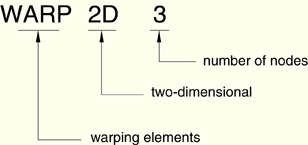
For example, WARP2D4 is 4-node warping element in two dimensions.
You use a solid section definition to define the section properties. You must associate these properties with a region of your model. No additional data are necessary.
| Input File Usage: | *SOLID SECTION, ELSET=name |
where the ELSET parameter refers to a set of warping elements. |
You must associate a linear elastic material definition with each warping element section definition. Optionally, you can associate a material orientation definition with the section (see “Orientations,” Section 2.2.5).
Only isotropic linear elasticity (“Defining isotropic elasticity” in “Linear elastic behavior,” Section 17.2.1) or orthotropic linear elasticity for warping elements (“Defining orthotropic elasticity for warping elements” in “Linear elastic behavior,” Section 17.2.1) are valid material models for warping elements.
| Input File Usage: | *SOLID SECTION, ELSET=name, MATERIAL=name, ORIENTATION=name |