4.8.1 Viscoelasticity

Products: ABAQUS/Standard ABAQUS/Explicit
The basic hereditary integral formulation for linear isotropic viscoelasticity is
Here

and

are the mechanical deviatoric and volumetric strains;
K is the bulk modulus and
G is the shear modulus, which are functions of the reduced time

; and

denotes differentiation with respect to

.
The reduced time is related to the actual time through the integral differential equation
where

is the temperature and

is the shift function. (Hence, if

,

.) A commonly used shift function is the Williams-Landell-Ferry (WLF) equation, which has the following form:
where

and

are constants and

is the “glass” transition temperature. This is the temperature at which, in principle, the behavior of the material changes from glassy to rubbery. If

, deformation changes will be elastic.

and

were once thought to be “universal” constants whose values were obtained at

, but these constants have been shown to vary slightly from polymer to polymer.
ABAQUS allows the WLF equation to be used with any convenient temperature, other than the glass transition temperature, as the reference temperature. The form of the equation remains the same, but the constants are different. Namely,
where

is the reference temperature at which the relaxation data are given, and

and

are the calibration constants at the reference temperature. The “universal” constants

and

are related to

and

as follows:
Other forms of

are also used, such as a power series in

. ABAQUS allows a general definition of the shift function with user subroutine
UTRS.
The relaxation functions  and
and  can be defined individually in terms of a series of exponentials known as the Prony series:
where

and

represent the long-term bulk and shear moduli. In general, the relaxation times

and

need not equal each other; however, ABAQUS assumes that

. On the other hand, the number of terms in bulk and shear,

and

, need not equal each other. In fact, in many practical cases it can be assumed that

. Hence, we now concentrate on the deviatoric behavior. The equations for the volumetric terms can be derived in an analogous way.
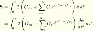
The deviatoric integral equation is
We rewrite this equation in the form
where

is the instantaneous shear modulus,

is the relative modulus of term
i, and
is the viscous (creep) strain in each term of the series. For finite element analysis this equation must be integrated over a finite increment of time. To perform this integration, we will assume that during the increment

varies linearly with

; hence,

. To use this relation, we break up
Equation 4.8.1–2 into two parts:
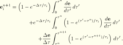
Now observe that
Use of this expression and the approximation for

during the increment yields
The first and last integrals in this expression are readily evaluated, whereas from
Equation 4.8.1–2 follows that the second integral represents the viscous strain in the

term at the beginning of the increment. Hence, the change in the

viscous strain is
If

approaches zero, this expression can be approximated by
The last form is used in the computations if

.
Hence, in an increment, Equation 4.8.1–3 or Equation 4.8.1–4 is used to calculate the new value of the viscous strains. Equation 4.8.1–1 is then used subsequently to obtain the new value of the stresses.
The tangent modulus is readily derived from these equations by differentiating the deviatoric stress increment, which is
with respect to the deviatoric strain increment

. Since the equations are linear, the modulus depends only on the reduced time step:
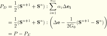
The energy dissipation follows from
with the total work
and the elastic energy increase
Finally, one needs a relation between the reduced time increment,  , and the actual time increment,
  . To do this, we observe that
  varies very nonlinearly with temperature; hence, any direct approximation of
  is likely to lead to large errors. On the other hand,
  will generally be a smoothly varying function of temperature that is well approximated by a linear function of temperature over an increment. If we further assume that incrementally the temperature
  is a linear function of time t, one finds the relation
or
with
This yields the relation
This expression can also be written as

Reduced states of stress

So far, we have discussed full triaxial stress states. If the stress state is reduced (i.e., plane stress or uniaxial stress), the equations derived here cannot be used directly because only the total stress state is reduced, not the individual terms in the series. Therefore, we use the following procedure.
For plane stress let the third component be the zero stress component. At the beginning of the increment we presumably know the volumetric elastic strain  , the volumetric viscous strain
  , and the volumetric viscous strains
  associated with the Prony series. The total volumetric strain can be obtained by adding together the elastic volumetric strain and the volumetric viscous strain
The deviatoric strain in the 3-direction follows from the relation

, which yields:
The out-of-plane deviatoric stress at the end of the increment is
Substituting
Equation 4.8.1–3 for

, letting

, and collecting terms gives
The hydrostatic stress is derived similarly as
We can write these equations in the form
In the third direction the deviatoric stress minus the hydrostatic pressure is zero; hence,
Since

, it follows that
from which

can be solved. One can then also calculate

and

, and with
Equation 4.8.1–3 or
Equation 4.8.1–4 one can update the deviatoric viscous strains

. The volumetric strains

are obtained with a relation similar to
Equation 4.8.1–3.
For uniaxial stress states a similar procedure is used. As before,  follows from Equation 4.8.1–5 and
  and
and  follow from
  :
:
Equation 4.8.1–6 and
Equation 4.8.1–7 can be used to calculate

and

, which again leads to
Equation 4.8.1–8. Applying
Equation 4.8.1–9 for

After this, one can follow the same procedure as for plane stress.
Automatic time stepping procedure

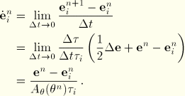
To create an automatic time stepping procedure in ABAQUS/Standard, we want to compare viscous strain rates at the beginning and the end of the increment. The strain rates in the individual terms at the beginning of the increment can be obtained directly by taking the limit of the incremental strain:
A similar expression can be derived for the strain rate at the end of the increment:
If we use these expressions to calculate a difference in estimated total viscous strain increment, one finds
This expression is readily evaluated. A similar expression can be calculated for volumetric strain  , and from these two quantities a suitable scalar measure can be constructed; for example,
Comparison with the user-specified strain increment tolerance allows construction of an automatic time stepping scheme.

![]()
![]()
![]()
![]()

![]() and
and ![]() can be defined individually in terms of a series of exponentials known as the Prony series:
can be defined individually in terms of a series of exponentials known as the Prony series: ![]()


![]()


![]()
![]()
![]() , and the actual time increment,
, and the actual time increment, ![]() . To do this, we observe that
. To do this, we observe that ![]() varies very nonlinearly with temperature; hence, any direct approximation of
varies very nonlinearly with temperature; hence, any direct approximation of ![]() is likely to lead to large errors. On the other hand,
is likely to lead to large errors. On the other hand, ![]() will generally be a smoothly varying function of temperature that is well approximated by a linear function of temperature over an increment. If we further assume that incrementally the temperature
will generally be a smoothly varying function of temperature that is well approximated by a linear function of temperature over an increment. If we further assume that incrementally the temperature ![]() is a linear function of time t, one finds the relation
is a linear function of time t, one finds the relation ![]()
![]()


![]()

![]() , the volumetric viscous strain
, the volumetric viscous strain ![]() , and the volumetric viscous strains
, and the volumetric viscous strains ![]() associated with the Prony series. The total volumetric strain can be obtained by adding together the elastic volumetric strain and the volumetric viscous strain
associated with the Prony series. The total volumetric strain can be obtained by adding together the elastic volumetric strain and the volumetric viscous strain ![]()

![]()
![]()
![]() follows from Equation 4.8.1–5 and
follows from Equation 4.8.1–5 and ![]() and
and ![]() follow from
follow from ![]() :
: ![]()


![]()

![]() , and from these two quantities a suitable scalar measure can be constructed; for example,
, and from these two quantities a suitable scalar measure can be constructed; for example, ![]()