Products: ABAQUS/CAE ABAQUS/Viewer
Benefits: Minor changes have been made in the Visualization module to enhance the usability of the rotate tool and the local coordinate systems used to control camera movement.
Description: When you select a node as the center of rotation for rotating the model view, the node value is saved. As you switch between undeformed and deformed model views and manipulate the model, the center of rotation now moves with the deformation of the selected node rather than remaining at the location of the node where you selected it.
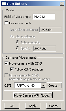
When you select camera movement options to modify the current view, you must select a local coordinate system. The View Options dialog box now includes two buttons that allow you to quickly create a new coordinate system. The new buttons to create coordinate systems are shown in Figure 14–10. The Create button opens the Create Coordinate System dialog box so that you can select the type of coordinate system that you want to create. Use the Move Camera With Node button to select a node from the viewport; ABAQUS/CAE creates a moving rectangular coordinate system using the name and location of the selected node. The coordinate system that you create is selected automatically as the local system for camera movement. You can also create a local coordinate system for the camera or reset the camera to the global coordinate system using the ![]() and
and ![]() buttons, respectively, in the context bar. If you want the camera to follow the rotation of the local coordinate system as well as its position, toggle on Follow CSYS rotation.
buttons, respectively, in the context bar. If you want the camera to follow the rotation of the local coordinate system as well as its position, toggle on Follow CSYS rotation.
Visualization module: ViewRotate: Select: Pick a node from the viewport View