ABAQUS/CAE is the Complete ABAQUS Environment that provides a simple, consistent interface for creating ABAQUS models, interactively submitting and monitoring ABAQUS jobs, and evaluating results from ABAQUS simulations. ABAQUS/CAE is divided into modules, where each module defines a logical aspect of the modeling process; for example, defining the geometry, defining material properties, and generating a mesh. As you move from module to module, you build up the model. When the model is complete, ABAQUS/CAE generates an input file that you submit to the ABAQUS analysis product. ABAQUS/Standard or ABAQUS/Explicit reads the input file generated by ABAQUS/CAE, performs the analysis, sends information to ABAQUS/CAE to allow you to monitor the progress of the job, and generates an output database. Finally, you use the Visualization module to read the output database and view the results of your analysis.
To start ABAQUS/CAE, you enter the command
abaqus caeat your operating system prompt, where abaqus is the command used to run ABAQUS. This command may be different on your system.
When ABAQUS/CAE begins, the Start Session dialog box appears as shown in Figure 2–1. The following session startup options are available:
Create Model Database allows you to begin a new analysis.
Open Database allows you to open a previously saved model or output database file.
Run Script allows you to run a file containing ABAQUS/CAE commands.
Start Tutorial allows you to begin an introductory tutorial from the online documentation.
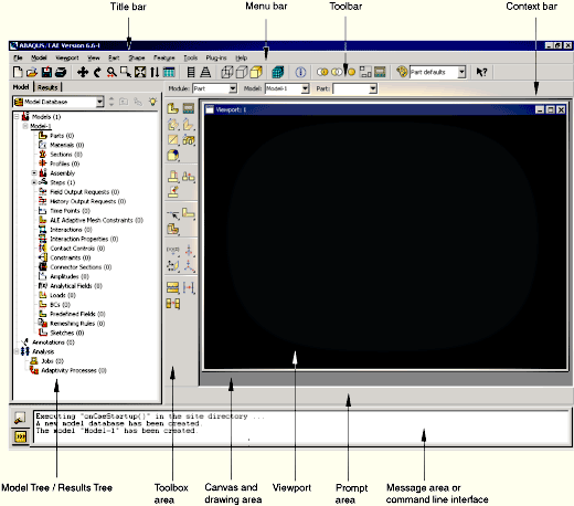
You interact with ABAQUS/CAE through the main window. Figure 2–2 shows the components that appear in the main window.
The components are:Title bar
The title bar indicates the version of ABAQUS/CAE you are running and the name of the current model database.
Menu bar
The menu bar contains all the available menus; the menus give access to all the functionality in the product. Different menus appear in the menu bar depending on which module you selected from the context bar. For more information, see “Components of the main menu bar,” Section 2.2.2 of the ABAQUS/CAE User's Manual.
Toolbar
The toolbar provides quick access to items that are also available in the menus. For more information, see “Components of the toolbar,” Section 2.2.3 of the ABAQUS/CAE User's Manual.
Context bar
ABAQUS/CAE is divided into a set of modules, where each module allows you to work on one aspect of your model; the Module list in the context bar allows you to move between these modules. Other items in the context bar are a function of the module in which you are working; for example, the context bar allows you to retrieve an existing part while creating the geometry of the model. For more information, see “The context bar,” Section 2.2.4 of the ABAQUS/CAE User's Manual.
Model Tree
The Model Tree provides you with a graphical overview of your model and the objects that it contains, such as parts, materials, steps, loads, and output requests. In addition, the Model Tree provides a convenient, centralized tool for moving between modules and for managing objects. If your model database contains more than one model, you can use the Model Tree to move between models. When you become familiar with the Model Tree, you will find that you can quickly perform most of the actions that are found in the main menu bar, the module toolboxes, and the various managers. For more information, see “Working with the Model Tree and the Results Tree,” Section 3.5 of the ABAQUS/CAE User's Manual.
Results Tree
The Results Tree provides you with a graphical overview of your output databases and other session-specific data such as X–Y plots. If you have more than one output database open in your session, you can use the Results Tree to move between output databases. When you become familiar with the Results Tree, you will find that you can quickly perform most of the actions in the Visualization module that are found in the main menu bar and the toolbox. For more information, see “An overview of the Results Tree,” Section 3.5.2 of the ABAQUS/CAE User's Manual.
Toolbox area
When you enter a module, the toolbox area displays tools in the toolbox that are appropriate for that module. The toolbox allows quick access to many of the module functions that are also available from the menu bar. For more information, see “Understanding and using toolboxes,” Section 3.3 of the ABAQUS/CAE User's Manual.
Canvas and drawing area
The canvas can be thought of as an infinite screen or bulletin board on which you post viewports; for more information, see Chapter 4, “Managing viewports on the canvas,” of the ABAQUS/CAE User's Manual. The drawing area is the visible portion of the canvas.
Viewport
Viewports are windows on the canvas in which ABAQUS/CAE displays your model. For more information, see Chapter 4, “Managing viewports on the canvas,” of the ABAQUS/CAE User's Manual.
Prompt area
The prompt area displays instructions for you to follow during a procedure; for example, it asks you to select the geometry as you create a set. For more information, see “Using the prompt area during procedures,” Section 3.1 of the ABAQUS/CAE User's Manual.
Message area
ABAQUS/CAE prints status information and warnings in the message area. To resize the message area, drag the top edge; to see information that has scrolled out of the message area, use the scroll bar on the right side. The message area is displayed by default, but it uses the same space occupied by the command line interface. If you have recently used the command line interface, you must click the ![]() tab in the bottom left corner of the main window to activate the message area.
tab in the bottom left corner of the main window to activate the message area.
Note: If new messages are added while the command line interface is active, ABAQUS/CAE changes the background color surrounding the message area icon to red. When you display the message area, the background reverts to its normal color.
Command line interface
You can use the command line interface to type Python commands and evaluate mathematical expressions using the Python interpreter that is built into ABAQUS/CAE. The interface includes primary (>>>) and secondary (...) prompts to indicate when you must indent commands to comply with Python syntax.
The command line interface is hidden by default, but it uses the same space occupied by the message area. Click the ![]() tab in the bottom left corner of the main window to switch from the message area to the command line interface. Click the
tab in the bottom left corner of the main window to switch from the message area to the command line interface. Click the ![]() tab to return to the message area.
tab to return to the message area.
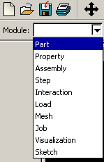
As mentioned earlier, ABAQUS/CAE is divided into functional units called modules. Each module contains only those tools that are relevant to a specific portion of the modeling task. For example, the Mesh module contains only the tools needed to create finite element meshes, while the Job module contains only the tools used to create, edit, submit, and monitor analysis jobs.
You select a module from the Module list in the context bar, as shown in Figure 2–3.
The order of the modules in the menu corresponds to a logical sequence you may follow to create a model. In many circumstances you must follow this natural progression to complete a modeling task; for example, you must create parts before you create an assembly. Although the order of the modules follows a logical sequence, ABAQUS/CAE allows you to select any module at any time, regardless of the state of your model. However, certain obvious restrictions apply; for example, you cannot assign section properties, such as cross-sectional dimensions of an I-beam, to geometry that has not yet been created.A completed model contains everything that ABAQUS needs to start the analysis. ABAQUS/CAE uses a model database to store your models. When you start ABAQUS/CAE, the Start Session dialog box allows you to create a new, empty model database in memory. After you start ABAQUS/CAE, you can save your model database to a disk by selecting File![]() Save from the main menu bar; to retrieve a model database from a disk, select File
Save from the main menu bar; to retrieve a model database from a disk, select File![]() Open.
Open.
The following list of the modules available within ABAQUS/CAE briefly describes the modeling tasks you can perform in each module. The order of the modules in the list corresponds to the order of the modules in the context bar's Module list (see Figure 2–3):
Part
The Part module allows you to create individual parts by sketching their geometry directly in ABAQUS/CAE or by importing their geometry from other geometric modeling programs. For more information, see Chapter 11, “The Part module,” of the ABAQUS/CAE User's Manual.
Property
A section definition contains information about the properties of a part or a region of a part, such as a region's associated material definition and cross-sectional geometry. In the Property module you create section and material definitions and assign them to regions of parts. For more information, see Chapter 12, “The Property module,” of the ABAQUS/CAE User's Manual.
Assembly
When you create a part, it exists in its own coordinate system, independent of other parts in the model. You use the Assembly module to create instances of your parts and to position the instances relative to each other in a global coordinate system, thus creating an assembly. An ABAQUS model contains only one assembly. For more information, see Chapter 13, “The Assembly module,” of the ABAQUS/CAE User's Manual.
Step
You use the Step module to create and configure analysis steps and associated output requests. The step sequence provides a convenient way to capture changes in a model (such as loading and boundary condition changes); output requests can vary as necessary between steps. For more information, see Chapter 14, “The Step module,” of the ABAQUS/CAE User's Manual.
Interaction
In the Interaction module you specify mechanical and thermal interactions between regions of a model or between a region of a model and its surroundings. An example of an interaction is contact between two surfaces. Other interactions that may be defined include constraints, such as tie, equation, and rigid body constraints. ABAQUS/CAE does not recognize mechanical contact between part instances or regions of an assembly unless that contact is specified in the Interaction module; the mere physical proximity of two surfaces in an assembly is not sufficient to indicate any type of interaction between the surfaces. Interactions are step-dependent objects, which means that you must specify the analysis steps in which they are active. For more information, see Chapter 15, “The Interaction module,” of the ABAQUS/CAE User's Manual.
Load
The Load module allows you to specify loads, boundary conditions, and predefined fields. Loads and boundary conditions are step-dependent objects, which means that you must specify the analysis steps in which they are active; some predefined fields are step-dependent, while others are applied only at the beginning of the analysis. For more information, see Chapter 16, “The Load module,” of the ABAQUS/CAE User's Manual.
Mesh
The Mesh module contains tools that allow you to generate a finite element mesh on an assembly created within ABAQUS/CAE. Various levels of automation and control are available so that you can create a mesh that meets the needs of your analysis. For more information, see Chapter 17, “The Mesh module,” of the ABAQUS/CAE User's Manual.
Job
Once you have finished all of the tasks involved in defining a model, you use the Job module to analyze your model. The Job module allows you to interactively submit a job for analysis and monitor its progress. Multiple models and runs may be submitted and monitored simultaneously. For more information, see Chapter 18, “The Job module,” of the ABAQUS/CAE User's Manual.
Visualization
The Visualization module provides graphical display of finite element models and results. It obtains model and result information from the output database; you can control what information is written to the output database by modifying output requests in the Step module. For more information, see Part V, “Viewing results,” of the ABAQUS/CAE User's Manual.
Sketch
Sketches are two-dimensional profiles that are used to help form the geometry defining an ABAQUS/CAE native part. You use the Sketch module to create a sketch that defines a planar part, a beam, or a partition or to create a sketch that might be extruded, swept, or revolved to form a three-dimensional part. For more information, see Chapter 19, “The Sketch module,” of the ABAQUS/CAE User's Manual.
The contents of the main window change as you move between modules. Selecting a module from the Module list on the context bar causes the context bar, module toolbox, and menu bar to change to reflect the functionality of the current module.
Each module is discussed in more detail in the tutorial examples presented in this manual.
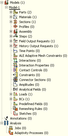
The Model Tree provides a visual description of the hierarchy of items in a model. It is located in the left side of the main window underneath the Model tab. Figure 2–4 shows a typical Model Tree.
Items in the Model Tree are represented by small icons; for example, the Steps icon,![]() . In addition, parentheses next to an item indicate that the item is a container, and the number in the parentheses indicates the number of items in the container. You can click on the “
. In addition, parentheses next to an item indicate that the item is a container, and the number in the parentheses indicates the number of items in the container. You can click on the “![]() ” and “–” signs in the Model Tree to expand and collapse a container. The right and left arrow keys perform the same operation.
” and “–” signs in the Model Tree to expand and collapse a container. The right and left arrow keys perform the same operation.
The arrangement of the containers and items in the Model Tree reflects the order in which you are expected to create your model. As noted earlier, a similar logic governs the order of modules in the module menu—you create parts before you create the assembly, and you create steps before you create loads. This arrangement is fixed—you cannot move items in the Model Tree.
The Model Tree provides most of the functionality of the main menu bar and the module managers. For example, if you double-click on the Parts container, you can create a new part (the equivalent of selecting Part![]() Create from the main menu bar).
Create from the main menu bar).
The instructions for the examples discussed in this manual will focus on using the Model Tree to access the functionality of ABAQUS/CAE. Menu bar actions will be considered only when necessary (e.g., when creating a finite element mesh or postprocessing results).
The Results Tree uses the same space occupied by the Model Tree. Click the Results tab in the left side of the main window to switch from the Model Tree to the Results Tree. The Results Tree provides access to session-specific features (i.e., functionality available in only the Visualization module). The Results Tree will be introduced during the course of the postprocessing exercises contained in this manual.