To start the tutorial, you create the first part—half of the hinge. ABAQUS/CAE models are composed of features; you create a part by combining features. This portion of the hinge is composed of the following features:
A cube—the base feature, since it is the first feature of the part.
A flange that extends from the cube. The flange also includes a large-diameter hole through which the pin is inserted.
A small lubrication hole in one corner of the flange.
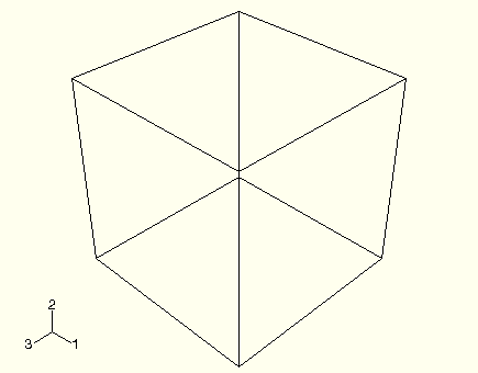
To create the cube (the base feature), you create a solid, three-dimensional, extruded part and name it. You then sketch its profile (0.04 m × 0.04 m) and extrude the profile over a specified distance (0.04 m) to produce the base feature of the first half of the hinge. The desired cube is shown in Figure C–2.
Note: The default render style used throughout ABAQUS/CAE is Shaded. For clarity, many of the figures in this tutorial use the wireframe or hidden line render styles. For more information, see “Choosing a render style,” Section 50.2 of the ABAQUS/CAE User's Manual.
To create the cube:
Start ABAQUS/CAE, and create a new model database. Resize your windows so that you can follow the tutorial and see the ABAQUS/CAE main window.
ABAQUS/CAE enters the Part module and displays the Model Tree in the left side of the main window.
In the Model Tree, double-click the Parts container to create a new part.
The Create Part dialog box appears.
The text in the prompt area asks you to fill out the Create Part dialog. ABAQUS/CAE always displays prompts in the prompt area to guide you through a procedure.
Name the part Hinge-hole. Accept the following default settings:
A three-dimensional, deformable body
A solid extrusion base feature
In the Approximate size text field, type 0.2. You will be modeling the hinge using meters for the unit of length, and its overall length is 0.14 meters; therefore, 0.2 meters is a sufficiently large approximate size for the part. Click Continue to create the part.
The Sketcher starts and displays the toolbox between the canvas and the Model Tree. ABAQUS/CAE uses the approximate size of the part to compute the default sheet size—0.2 meters in this example. In addition, in this example the Sketcher draws 40 grid lines on the sheet, and the distance between each grid line is 0.005 meters. (You probably see fewer than 40 grid lines because the sheet extends beyond your viewport.)
From the Sketcher toolbox, select the rectangle tool ![]() .
.
Sketch an arbitrary rectangle, and click mouse button 2 in the viewport to exit the rectangle tool.
Dimension the top and left edges so that each is 0.04 m long.
Important: To complete this tutorial successfully, it is important that you use the dimensions stated and do not deviate from the example; otherwise, you will find it difficult to assemble the model.
Click mouse button 2 to exit the Sketcher.
Tip: Clicking mouse button 2 in the viewport has the same effect as clicking the default button in the prompt area—Done in this instance.
In the dialog box, type a Depth of 0.04 and press [Enter].
ABAQUS/CAE exits the Sketcher and displays the base feature, a cube, as shown in Figure C–2. The triad in the lower-left corner of the viewport indicates the orientation of the X-, Y-, and Z-axes. You can turn off this triad by selecting Viewport![]() Viewport Annotation Options from the main menu bar and toggling off the Show triad option. (The triad is sometimes turned off for clarity in the figures in this tutorial.)
Viewport Annotation Options from the main menu bar and toggling off the Show triad option. (The triad is sometimes turned off for clarity in the figures in this tutorial.)
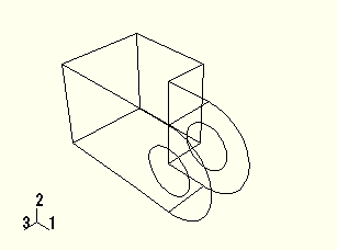
You will now add a solid feature—the flange—to the base feature. You select one face of the cube to define the sketch plane and extrude the sketched profile through half the depth of the cube. The cube and flange are shown in Figure C–3.
To add the flange to the base feature:
From the main menu bar, select Shape![]() Solid
Solid![]() Extrude.
Extrude.
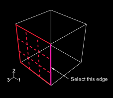
Select a face to define the sketching plane. Select the face at the front of the cube, as shown in Figure C–4.
Figure C–4 Select the gridded face to define the sketching plane. Select the indicated edge to position the part correctly in the Sketcher.
When you stop moving the cursor during a selection procedure, ABAQUS/CAE highlights the edges of the entity that it would select at the current cursor position. This highlighting behavior is called “preselection.”
Note: Two forms of preselection are available in ABAQUS/CAE: one for object selection from the viewport and the other for selection from the Sketcher. For more information, see “Highlighting objects prior to selection,” Section 6.3.4 of the ABAQUS/CAE User's Manual, and “Turning preselection on or off,” Section 19.9.3 of the ABAQUS/CAE User's Manual, respectively.
Select an edge that will appear vertical and on the right side of the sketch, as shown in Figure C–4.
Again, ABAQUS/CAE uses preselection to aid you in selecting the desired edge.
The Sketcher starts and displays the outline of the base feature as reference geometry. ABAQUS/CAE magnifies the view to fit the sketch plane; the sheet size and grid spacing are also recalculated based on the size of the sketch plane. To change the sheet size and grid spacing back to their original settings and disable their automatic recalculation for the current session, use the options tool ![]() , located in the Sketcher toolbox. On the General tabbed page, toggle off Auto next to the sheet size text field and set the value to 0.2; toggle off Auto next to the grid spacing text field and set the value to 0.005.
, located in the Sketcher toolbox. On the General tabbed page, toggle off Auto next to the sheet size text field and set the value to 0.2; toggle off Auto next to the grid spacing text field and set the value to 0.005.
Tip: To retain the original sheet size and grid spacing for all sketches in a part, you can select the options tool while sketching the base feature—the cube—and toggle off both Auto settings.
Zoom out to view the area where you will sketch the flange:
From the toolbar, select the magnify tool ![]() .
.
Position the cursor near the center of the viewport.
Click mouse button 1 and drag to the left until the cube occupies approximately half of the visible Sketcher space.
Reducing the view is necessary because the flange is created beyond the edges of the selected sketch plane.
As before, the approximate shape of the new feature will be sketched first. From the Sketcher toolbox, select the connected lines tool ![]() .
.
Sketch the rectangular portion of the flange by drawing three lines as follows:
Starting at any point to the right of the cube, connect the line to the top-right corner of the cube.
Continue the next line to the bottom-right corner of the cube. This line is automatically assigned a vertical constraint.
The final line extends from the bottom-right corner of the cube to any point to the right of the cube.
Tip:
If you make a mistake while sketching, use the Sketcher undo ![]() or delete
or delete ![]() tools to correct your error.
tools to correct your error.
Click mouse button 2 in the viewport to exit the connected lines tool.
Refine the sketch by defining the following constraints and dimension:
Use the constraints tool ![]() to constrain the top and bottom lines of the sketch so that each is horizontal.
to constrain the top and bottom lines of the sketch so that each is horizontal.
Assign an equal length constraint to these two lines (use [Shift]+Click to select both lines).
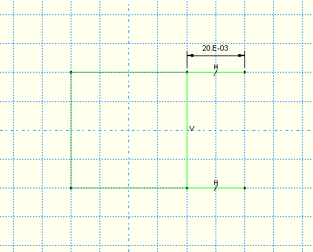
Dimension either line so that it is 0.02 m long.
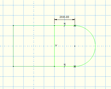
The sketch appears as shown in Figure C–6.
Close the profile by adding a semicircular arc using the 3-points circle tool ![]() .
.
Select the two vertices at the open end of the rectangle as the endpoints of the arc, starting with the top one. Select any point to the right of the sketch as a point that lies on the arc.
Define tangent constraints between the ends of the arc and the horizontal lines to refine the sketch.
Click mouse button 2 in the viewport to exit the 3-points circle tool.
The resulting arc is shown in Figure C–7.
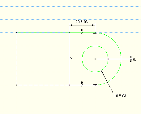
From the Sketcher toolbox, select the center-perimeter circle tool ![]() to sketch the flange hole.
to sketch the flange hole.
The center of the circle should coincide with the center of the arc created previously. The perimeter point should be placed to the right of the center point.
Use the dimension tool ![]() to change the value of the radius to 0.01 m.
to change the value of the radius to 0.01 m.
Dimension the vertical distance between the center of the circle and the perimeter point. Edit this dimension so that the distance is 0. (If the distance is already 0, you cannot add a vertical dimension.) This will adjust the location of the perimeter point so that it is on the same horizontal plane as the center point.
Note: When you mesh a part, ABAQUS/CAE places nodes wherever vertices appear along an edge; therefore, the location of the vertex on the circumference of the circle influences the final mesh. Placing it on the same horizontal plane as the center point results in a high-quality mesh.
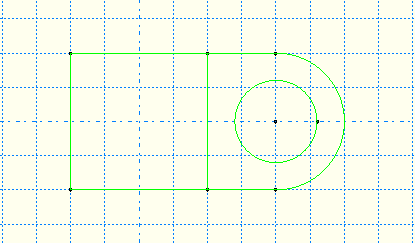
The final sketch is shown in Figure C–8.
Click mouse button 2 to exit the Sketcher.
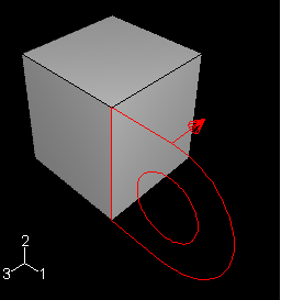
ABAQUS/CAE displays the part in an isometric view showing the base extrusion, your sketched profile, and an arrow indicating the extrusion direction. The default extrusion direction for a solid is always out of the solid. ABAQUS/CAE also displays the Edit Extrusion dialog box.
Tip:
Use the auto-fit view manipulation tool ![]() to fit the sketched flange profile and the base extrusion in the viewport.
to fit the sketched flange profile and the base extrusion in the viewport.
In the Edit Extrusion dialog box:
Accept the default Type selection of Blind to indicate that you will provide the depth of the extrusion.
In the Depth field, type an extrusion depth of 0.02.
Click Flip to reverse the extrusion direction, as shown in Figure C–9.
Toggle on Keep internal boundaries. When you toggle this option on, ABAQUS/CAE maintains the face that is generated between the extruded solid feature and the existing part. As a result, the extruded flange is maintained as a second cell and is not merged with the cube. (When you mesh the model at the end of the tutorial, the internal boundary allows you to mesh the flange without having to first partition the cell and flange into separate cells.)
Click OK to create the solid extrusion.
ABAQUS/CAE displays the part composed of the cube and the flange. Use the auto-fit view manipulation tool ![]() again to resize the part to fit in the viewport.
again to resize the part to fit in the viewport.
Each part is defined by a set of features, and each feature in turn is defined by a set of parameters. For example, the base feature (the cube) and the second feature (the flange) are both defined by a sketch and an extrusion depth. You modify a part by modifying the parameters that define its features. For the hinge example you will change the radius of the hole in the sketch of the flange from 0.01 m to 0.012 m.
To modify a feature:
In the Model Tree, expand the Hinge-hole item underneath the Parts container. Then expand the Features container that appears.
A list showing each feature's Name appears. In this example you have created two solid extrusion features: the base feature (the cube), Solid extrude-1, and the flange, Solid extrude-2.
Click mouse button 3 on Solid extrude-2 (the flange) in this list.
ABAQUS/CAE highlights the selected feature in the viewport.
From the menu that appears, select Edit.
ABAQUS/CAE displays the feature editor. For an extruded solid you can change the extrusion depth, the twist or draft (if specified when the feature was created), and the profile sketch.
From the feature editor, click Edit Section Sketch.
ABAQUS/CAE displays the sketch of the second feature, and the feature editor disappears.
From the edit tools in the Sketcher toolbox, select the edit dimension value tool ![]() .
.
Select the radial dimension of the circle (0.010).
In the Edit Dimension dialog box, type a new radius of 0.012 and click OK.
ABAQUS/CAE closes the dialog box and changes the radius of the circle in the sketch only.
Click mouse button 2 to exit the edit dimension value tool. Click mouse button 2 again to exit the Sketcher.
ABAQUS/CAE again displays the feature editor.
Click OK to regenerate the flange with the modified radius and to exit the feature editor.
The flange hole is enlarged to the new radius dimension.
Note: In some circumstances regenerating a feature causes dependent features to fail. In such a case ABAQUS/CAE asks if you want to save your changes and suppress the features that failed to regenerate, or if you want to revert to the unmodified feature and lose your changes.
The flange includes a small hole used for lubrication, as shown in Figure C–10.
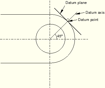
Creating the hole in the desired location requires an appropriate datum plane on which to sketch the profile of the extruded cut, as shown in Figure C–11. You sketch a circle on the datum plane, which is tangent to the flange, and ABAQUS/CAE extrudes the circle normal to the datum plane and normal to the flange to create the lubrication hole.There are three operations involved in creating the datum plane:
Creating a datum point on the circumference of the flange.
Creating a datum axis running between two datum points.
Creating a datum plane through the datum point on the circumference and normal to the datum axis.
To create the sketch plane:
From the main menu bar, select Tools![]() Datum.
Datum.
ABAQUS/CAE displays the Create Datum dialog box.
Create a datum point along the curved edge of the flange through which the datum plane will pass. From the Create Datum dialog box, choose the Point datum type.
From the list of methods, select Enter parameter, and click Apply.
Note: What is the difference between the OK and Apply buttons? When you click OK, the Create Datum dialog box closes before you create the datum. When you click Apply, the Create Datum dialog box remains open while you create the datum and is available for you to create the next datum. Click OK if you want to create only a single datum; click Apply if you want to create several pieces of datum geometry before moving on to a new procedure.
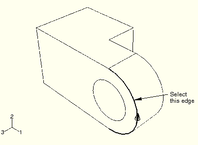
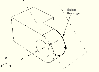
Select the curved edge, as shown in Figure C–12. Note the direction of the arrow indicating an increasing edge parameter from 0.0 to 1.0. You cannot change the direction of this arrow.
In the text box in the prompt area, enter a normalized edge parameter and press [Enter]. If the arrow direction is the same as in Figure C–12, enter 0.75 as the normalized edge parameter; if the arrow points in the opposite direction, enter 0.25 as the normalized edge parameter.
ABAQUS/CAE creates a datum point along the selected edge.
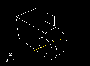
Create a datum axis that will define the normal to the datum plane. From the Create Datum dialog box, choose the Axis datum type. Select the 2 points method, and click Apply.
ABAQUS/CAE highlights the points that can be used to create the datum axis.
Select the point at the center of the hole (created when you sketched the hole's profile) and the datum point on the curved edge.
ABAQUS/CAE displays a datum axis passing through the two points, as shown in Figure C–13.
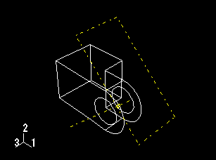
The final step is to create the datum plane normal to the datum axis. From the Create Datum dialog box, choose the Plane datum type. Select the Point and normal method, and click OK.
Select the datum point on the curved edge as the point through which the datum plane will pass.
Select the datum axis as the edge that will be normal to the datum plane.
ABAQUS/CAE creates the datum plane, as shown in Figure C–14.
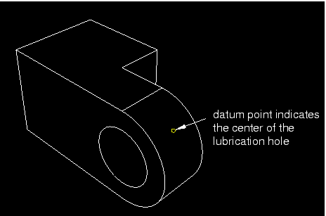
The next operation creates the lubrication hole on the flange by extruding a circle from the datum plane that you just created. First, you need to create a datum point on the flange that indicates the center of the hole, as illustrated in Figure C–15.
To create the datum point at the center of the lubrication hole:
From the main menu bar, select Tools![]() Datum.
Datum.
ABAQUS/CAE displays the Create Datum dialog box.
Create a datum point along the second curved edge of the flange. From the Create Datum dialog box, choose the Point datum type.
From the list of methods, select Enter parameter, and click Apply.
Select the second curved edge of the flange, as shown in Figure C–16.
Note the direction of the arrow indicating an increasing edge parameter from 0.0 to 1.0. Enter a normalized edge parameter of 0.75 (or 0.25 if the sense of the arrow is opposite that shown in Figure C–16), and press [Enter].
ABAQUS/CAE creates a datum point along the selected edge.
From the list of methods, select Midway between 2 points, and click OK.
Select the datum point along the first curved edge.
Select the datum point along the second curved edge.
ABAQUS/CAE creates a datum point halfway across the flange and closes the Create Datum dialog box. This exercise illustrates how you can use feature-based modeling to capture your design intent. The datum point is a feature that ABAQUS/CAE defines to be midway between the datum points along the edges of the flange. As a result, if you change the thickness of the flange, the lubrication hole remains in the center.
To sketch the lubrication hole:
From the main menu bar, select Shape![]() Cut
Cut![]() Extrude.
Extrude.
Click the boundary of the datum plane to select it as the plane on which to sketch.
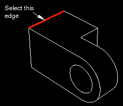
Select the top rear edge of the cube as the edge that will appear vertical and on the right side of the sketch, as shown in Figure C–17.
The Sketcher starts with the vertices, datums, and edges of the part projected onto the sketch plane as reference geometry.
Tip:
If you are unsure of the relative orientation of the sketch plane and the part, use the view manipulation tools to rotate and pan them. Use the reset view tool ![]() to restore the original view.
to restore the original view.
From the Sketcher toolbox, select the circle tool ![]() .
.
Select the datum point on the center of the flange to indicate the center of the circle.
Select any other point, and click mouse button 1.
Dimension the radius of the hole. The radius of the circle should be changed to 0.003 m.
Dimension the vertical distance between the circle's center and perimeter points. Set this distance to zero. As noted earlier, this will improve the quality of the mesh.
Exit the Sketcher.
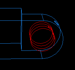
ABAQUS/CAE displays the hinge in an isometric view showing the base part and flange, your sketched hole profile, and an arrow indicating the direction for the extruded cut. ABAQUS/CAE also displays the Edit Cut Extrusion dialog box.
From the Type menu in the Edit Cut Extrusion dialog box, select Up to Face and click OK.
Select the cylindrical inner surface of the hole in the part to indicate the face to which to extrude, as illustrated in Figure C–18. (Because you can select at most only one face, ABAQUS/CAE does not ask you to indicate that you have finished selecting.)
ABAQUS/CAE extrudes the sketch from the datum plane to the hole in the flange.
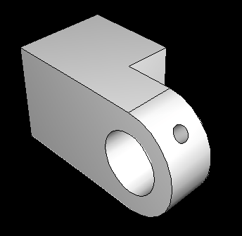
From the toolbar, select the shaded display tool ![]() if necessary, and use the rotation tool
if necessary, and use the rotation tool ![]() to see how the part and its features are oriented, as shown in Figure C–19. (For clarity, the datum geometry has been removed from the view in Figure C–19 by selecting View
to see how the part and its features are oriented, as shown in Figure C–19. (For clarity, the datum geometry has been removed from the view in Figure C–19 by selecting View![]() Part Display Options
Part Display Options![]() Datum.)
Datum.)
Tip:
After you rotate the part, use the cycle views tool ![]() to step through the previous views (up to a maximum of eight) and to restore the original view.
to step through the previous views (up to a maximum of eight) and to restore the original view.
Now that you have created the first part of your model, it is a good idea to save your model in a model database:
From the main menu bar, select File![]() Save. The Save Model Database As dialog box appears.
Save. The Save Model Database As dialog box appears.
Type a name for the new model database in the File Name field, and click OK. You do not need to include the file extension; ABAQUS/CAE appends .cae automatically to the file name.
ABAQUS/CAE stores the model database in a new file and returns to the Part module. The name of your model database appears in the main window title bar.
If you find you need to interrupt this tutorial, you can save the model database at any time and exit ABAQUS/CAE. You can then start a new ABAQUS/CAE session and open the saved model database by selecting Open Database from the Start Session dialog box. The model database will contain any parts, materials, loads, etc. that you created, and you will be able to continue the tutorial.