You will now generate the finite element mesh. You can choose the meshing technique that ABAQUS/CAE will use to create the mesh, the element shape, and the element type. ABAQUS/CAE uses a number of different meshing techniques. The default meshing technique assigned to the model is indicated by the color of the model when you enter the Mesh module; if ABAQUS/CAE displays the model in orange, it cannot be meshed without assistance from you.
In this section you will use the Mesh Controls dialog box to examine the technique that ABAQUS/CAE will use to mesh the model and the shape of the elements that ABAQUS/CAE will generate.
To assign the mesh controls:
In the Model Tree, expand the Beam item underneath the Parts container and double-click Mesh in the list that appears.
ABAQUS/CAE switches to the Mesh module. The Mesh module functionality is available only through menu bar items or toolbox icons.
From the main menu bar, select Mesh![]() Controls.
Controls.
The Mesh Controls dialog box appears. ABAQUS/CAE colors the regions of your model to indicate which technique it will use to mesh that region. ABAQUS/CAE will use structured meshing to mesh your cantilever beam and displays the beam in green.
In the dialog box, accept Hex as the default Element Shape selection.
Accept Structured as the default Technique selection.
Click OK to assign the mesh controls and to close the dialog box.
ABAQUS/CAE will use the structured meshing technique to create a mesh of hexahedral-shaped elements.
In this section you will use the Element Type dialog box to assign a particular ABAQUS element type to the model. Although you will assign the element type now, you could also wait until after the mesh has been created.
To assign an ABAQUS element type:
From the main menu bar, select Mesh![]() Element Type.
Element Type.
The Element Type dialog box appears.
In the dialog box, accept the following default selections that control the elements that are available for selection:
Standard is the default Element Library selection.
Linear is the default Geometric Order.
3D Stress is the default Family of elements.
In the lower portion of the dialog box, examine the element shape options. A brief description of the default element selection is available at the bottom of each tabbed page.
Since the model is a three-dimensional solid, only three-dimensional solid element types—hexahedral on the Hex tabbed page, triangular prism on the Wedge page, and tetrahedral on the Tet page—are shown.
Click the Hex tab, and choose Incompatible modes from the list of Element Controls.
A description of the element type C3D8I appears at the bottom of the dialog box. ABAQUS/CAE will now associate C3D8I elements with the elements in the mesh.
Click OK to assign the element type and to close the dialog box.
Basic meshing is a two-stage operation: first you seed the edges of the part instance, and then you mesh the part instance. You select the number of seeds based on the desired element size or on the number of elements that you want along an edge, and ABAQUS/CAE places the nodes of the mesh at the seeds whenever possible. For the cantilever beam tutorial the default seeding will generate a mesh with square hexahedral elements.
To mesh the model:
From the main menu bar, select Seed![]() Part to seed the part instance.
Part to seed the part instance.
The Global Seeds dialog box appears. The dialog box displays the default element size that ABAQUS/CAE will use to seed the part instance. This default element size is based on the size of the part instance.
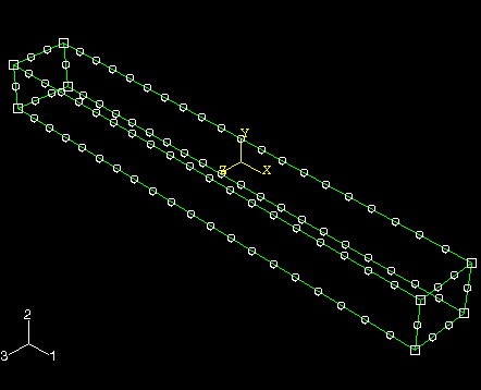
In the dialog box, enter an approximate global size of 10.0, and click OK.
ABAQUS/CAE applies the seeds to the part instance, as shown in Figure B–11. You can gain more control of the resulting mesh by seeding each edge of the part instance individually.
From the main menu bar, select Mesh![]() Part to mesh the part instance.
Part to mesh the part instance.
From the buttons in the prompt area, click Yes to confirm that you want to mesh the part instance.
ABAQUS/CAE meshes the part instance and displays the resulting mesh, as shown in Figure B–12.