Prescribed conditions, such as loads and boundary conditions, are step-dependent, which means that you must specify the step or steps in which they become active. Now that you have defined the steps in the analysis, you can define the following prescribed conditions:
A boundary condition that constrains one end of the cantilever beam in the X-, Y-, and Z-directions; the boundary condition is applied during the initial step.
A load that you apply to the top face of the beam; the load is applied during the general analysis step.
Create a boundary condition that constrains the cantilever beam to be built-in at one end of the beam.
To apply boundary conditions to one end of the cantilever beam:
In the Model Tree, double-click the BCs container.
ABAQUS/CAE switches to the Load module, and the Create Boundary Condition dialog box appears.
In the Create Boundary Condition dialog box:
Name the boundary condition Fixed.
From the list of steps, select Initial as the step in which the boundary condition will be activated.
In the Category list, accept Mechanical as the default category selection.
In the Types for Selected Step list, accept Symmetry/Antisymmetry/Encastre as the default type selection, and click Continue.
ABAQUS/CAE displays prompts in the prompt area to guide you through the procedure.
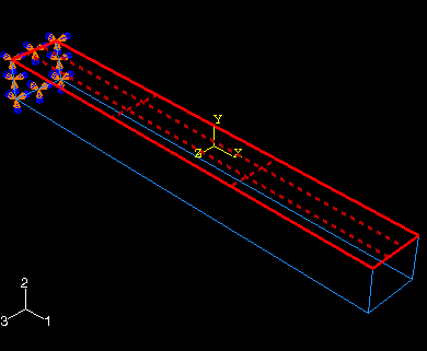
You will fix the face at the left end of the cantilever beam; the desired face is shown in Figure B–9.
By default, when you position the cursor over a region that overlaps more than one face ABAQUS/CAE highlights the face that is “closest” to the screen. To select the face at the left end of the cantilever beam without changing your view of the beam, you need to turn off this default behavior and cycle through the valid selections. Do the following:
From the prompt area, click the selection options tool ![]() .
.
From the Options dialog box that appears, toggle off the closest object tool ![]() .
.
Position the cursor over the desired face.
When you stop moving the cursor, ABAQUS/CAE highlights all faces that overlap at the cursor position. Ellipsis marks (...) appear to the right of the cursor arrow to indicate that the current selection is ambiguous.
Click mouse button 1 to accept the highlighted faces.
ABAQUS/CAE displays Next, Previous, and OK buttons in the prompt area.
Click Next and Previous until the desired face is highlighted.
Click OK to confirm your choice.
Click mouse button 2 in the viewport or click Done in the prompt area to indicate that you have finished selecting. The selection options return to their default behavior.
The Edit Boundary Condition dialog box appears.
In the dialog box:
Toggle on ENCASTRE.
Click OK to create the boundary condition and to close the dialog box.
ABAQUS/CAE displays arrows at each corner and midpoint on the selected face to indicate the constrained degrees of freedom. Single-headed arrows represent a constraint that is applied to a translational degree of freedom. Double-headed arrows represent a constraint that is applied to a rotational degree of freedom. An ENCASTRE boundary condition constrains all six degrees of freedom; however, in this model ABAQUS/CAE ignores the rotational constraints indicated by the double-headed arrows.
In the Model Tree, click mouse button 3 on the BCs container and select Manager from the menu that appears.
ABAQUS/CAE displays the Boundary Condition Manager. The manager indicates that the boundary condition is Created (activated) in the initial step and is Propagated (continues to be active) in the general analysis step BeamLoad.
Click Dismiss to close the Boundary Condition Manager.
Now that you have fixed one end of the cantilever beam, you can apply a distributed load to the top face of the beam. The load is applied during the general, static step you created earlier.
To apply a load to the top of the cantilever beam:
In the Model Tree, double-click the Loads container.
The Create Load dialog box appears.
In the Create Load dialog box:
Name the load Pressure.
From the list of steps, select BeamLoad as the step in which the load will be applied.
In the Category list, accept Mechanical as the default category selection.
In the Types for Selected Step list, select Pressure, and click Continue.
ABAQUS/CAE displays prompts in the prompt area to guide you through the procedure.
In the viewport, select the top face of the beam as the surface to which the load will be applied. The desired face is shown by the gridded face in Figure B–10.
Click mouse button 2 or click Done in the prompt area in the viewport to indicate that you have finished selecting regions.
The Edit Load dialog box appears.
In the dialog box:
Enter a magnitude of 0.5 for the load.
Accept the default Distribution selection—ABAQUS will apply the load uniformly over the face.
Accept the default Amplitude selection—ABAQUS will ramp up the load during the step.
Click OK to create the load and to close the dialog box.
ABAQUS/CAE displays downward-pointing arrows along the top face of the beam to indicate the load applied in the negative 2-direction.
Examine the Load Manager and note that the new load is “Created” (activated) in the general analysis step BeamLoad.
Click Dismiss to close the Load Manager.