Products: ABAQUS/Standard ABAQUS/Explicit
This example demonstrates how ABAQUS can be used to predict the long-duration response of submerged structures that experience loading by a wave resulting from an underwater explosion (UNDEX).
An emphasis on structural dynamic motions naturally leads to the use of beams to model the structure, rather than solid or shell elements. This class of problem is characterized by structural dynamic motions at speeds much slower than the acoustic wave speed in the fluid, so that the fluid can be modeled as an incompressible medium. The implication of modeling the fluid in this manner is to reduce its effect on the structure to an “added mass” on the beam.
The spherical pressure waves associated with an UNDEX event are characterized by two distinct phases. The first, very short, phase is the initial wave produced by the detonation. It involves a very steep rise to a characteristic pressure value, followed by a more gradual decay. In the second phase of the loading the gas produced by the explosive expands to a maximum volume, at which the pressure of the surrounding fluid forces it back upon itself. At some minimum volume the gas and fluid system emits another pressure pulse, and the gas bubble expands again. This process may repeat many times, causing several pressure pulses. As the gas bubble oscillates, it also acts under the effects of buoyancy, causing an unsteady motion opposite to the force of gravity.
This problem involves a structural-dynamics model of a submerged submarine under athwartships attack from an underwater explosion. The ship is 100 m in length and 50 m below the surface; and the detonation point of the charge is centered along the ship's length, 15 m to one side and 15 m below the ship. The response of the ship to the initial direct and reflected shock waves as well as to the first few bubble pulses is of interest, so dynamic simulations are carried out to 5 seconds.
The model is made of 100 B31 beam elements, arrayed along a line. Their (uniform) section properties are defined using the *BEAM GENERAL SECTION option. The structure has an overall length of 50 m. Point mass elements of 10000 kg are defined at each node to simulate the effect of internal equipment on the beam structural dynamics. The effect of the entrained fluid is simulated using the *BEAM FLUID INERTIA option, with which a fluid mass density of 1025 kg/m3, an outside radius of 5 m, and a fluid drag coefficient of 1.0 are specified. Structural damping is specified using the *DAMPING option. No additional acoustic fluid elements or absorbing boundary conditions are required.
The loading specification for this problem includes descriptions of the explosive charge, the fluid medium in which the wave propagates to the structure, and the geometry of the charge with respect to the structure.
In ABAQUS the time histories of pressure, its derivatives, and the motion of the explosive gas bubble are defined using the Geers-Hunter model. This model is invoked using the *AMPLITUDE, DEFINITION=BUBBLE option. Under this option material properties of the explosive, its mass, its distance from the free surface, and some other control parameters are specified. The data on this option are used to govern a separate bubble dynamics time integration operation, performed as part of the preprocessing. Parameters defined on this option do not affect the rest of the analysis. Here a charge of 100 kg is used, with model parameters set to suppress wave loss effects within the bubble simulation. An initial depth of 65 m is specified: this affects the oscillation of the gas bubble and the duration of the bubble dynamics, since the solution naturally terminates when the bubble reaches the free surface. In this analysis, however, the bubble simulation time is cut off at 0.6 seconds. The bubble migration is defined to be along the z-axis. Default values for the bubble dynamics time integration parameters are used.
The actual loads on the structure are defined using the *INCIDENT WAVE option and the associated *INCIDENT WAVE PROPERTY, *INCIDENT WAVE FLUID PROPERTY, and *INCIDENT WAVE REFLECTION options. The *INCIDENT WAVE option defines the distributed time-varying loads within an analysis step on the structural surface, due to the specified parameters. Only the surface defined for the beam elements and the reference load magnitude need to be indicated, as is the case for most distributed loads in ABAQUS. The *INCIDENT WAVE REFLECTION option defines any planes outside the computational domain for the purpose of calculating additional incident wave loads due to reflections. Here a “soft” (zero total pressure) reflecting plane is defined, located 65 m from the original position of the source and oriented normal to the z-axis. The remaining geometric and physical parameters defining the load are specified using the *INCIDENT WAVE PROPERTY and *INCIDENT WAVE FLUID PROPERTY options. The original position of the source point is defined as (50, 15, –15), and the standoff point is defined as (50, 3.536, –3.536). The fluid properties, used for propagation of the wave across the structure, are given as mass density ![]() = 1025 kg/m3 and bulk modulus
= 1025 kg/m3 and bulk modulus ![]() = 2.30635 GPa.
= 2.30635 GPa.
The model for this UNDEX example has a total of 606 active degrees of freedom and requires approximately 15 MB of memory and 267 KB of disk space.
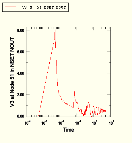
Figure 8.1.7–1 shows the time history of vertical displacement (V3) for the center node of the structure using a logarithmic time axis. This curve clearly shows the initial shock-induced velocity peak, the velocity peak caused by the reflected path, and the decaying periodic response associated with a structural motion after the loading ceases at t = 0.6. The response curve clearly illustrates that there is a rigid body translation of the cylinder, due to the velocity induced by the initial shocks. The peaks due to the direct and reflected shocks are of the same sign, since the reflected wave, with a negative sign, is travelling in the opposite vertical direction from the direct wave.
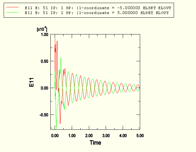
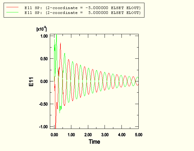
Figure 8.1.7–2 shows the strain along the axis of the beam for the section points oriented along the 1-direction of the section. The 1-direction is also the y-direction in the global system. The curves suggest that a dominant mode of vibration occurs at about 2.1 Hz (based on an estimated period of 0.48 seconds). Figure 8.1.7–3 shows the axial strain for section points oriented in the section 2-direction, or the global z-direction. Again, the two peaks corresponding to the incident shocks are evident, followed by the decaying oscillation at roughly 2.1 Hz.
ABAQUS/Standard analysis of a submerged cylinder subjected to an UNDEX shock wave.
ABAQUS/Explicit analysis of a submerged cylinder subjected to an UNDEX shock wave.