Product: ABAQUS/Explicit
This example illustrates the use of connector elements to model a cylinder-cam mechanism.
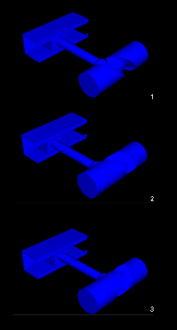
The cylinder-cam mechanism is shown in Figure 4.1.6–1. The solid aluminum cylinder is lying on the Z-axis and has a slot around its circumference. The centerline of the slot is defined by a plane intersecting the cylinder at 45 degrees. The slot has a radius of 7.62 mm (0.30 in) and a depth of 7.62 mm (0.30 in). A pin with a spherical end of radius 6.35 mm (0.25 in) is set into the slot. The pin is constrained to be parallel to the X-axis and remains in the X–Z plane. Because of the difference in radii, there is a 1.27 mm (0.05 in) gap between the slot and the pin head. As the cylinder rotates about the Z-axis, the pin travels in a track that is parallel to the cylinder. The pin has a weight of 13.34 N (3.0 lbf).
The cylinder rotates with a speed of 30 rpm, which drives the pin back and forth in the track. Resistance to the motion is caused by the friction between the pin and the track. The tolerance mismatch due to the pin head being smaller than the slot is considered in the model.
As shown in Figure 4.1.6–1, the track, the pin, and the cylinder are modeled using display bodies. The bodies in Figure 4.1.6–1 are connected as follows:
MASS and ROTARYI elements are attached to each display body through BEAM connector elements to account for the inertia of each part in the model.
The interaction between PIN and TRACK is modeled using ALIGN+SLOT connectors between point D and point E. The friction dissipation effects between PIN and TRACK are taken into account using the *CONNECTOR DAMPING option.
The interaction between PIN and CYLINDER is modeled by defining a CARTESIAN connector element between point B and point C. The 1.27 mm (0.05 in) gap between the pin and the slot is modeled using the *CONNECTOR STOP option. The local coordinate system of the CARTESIAN connector element (used to measure the displacement of point C relative to point B) is attached at point B to CYLINDER and has its 2–3 plane lying in the plane of the slot. The connector stop is defined along component 1 of the connector element. A displacement of 1.27 mm (0.05 in) of the pin relative to the center of the slot along the Z-axis corresponds to a displacement of point C relative to point B of 0.898 mm (0.035 in) in the connector local coordinate system. The connector stop is, thus, defined at a distance of 0.898 mm (0.035 in) in the positive and negative 1-directions of the CARTESIAN connector element.
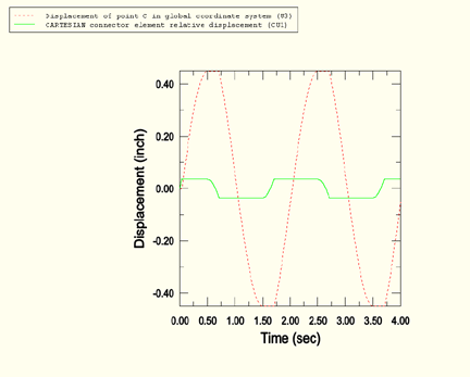
Figure 4.1.6–2 shows the positions of the mechanism as the cylinder is rotated. The time histories of the displacement of point C in the global coordinate system and the displacement of point C relative to point B in the CARTESIAN connector local coordinate system are shown in Figure 4.1.6–3. In the connector local coordinate system, point C travels a maximum distance of 0.035 in relative to point B. This corresponds to the value given in the connector stop definition. When PIN and CYLINDER are in contact, the displacement of point C relative to point B in the connector local coordinate system remains constant, and the cylinder forces the pin to translate. When contact is lost, the connector relative displacement varies with time, and the motion of the pin stops as a result of damping.
Python script that creates an ABAQUS/Explicit model using ABAQUS/CAE. The script imports the parts from an ACIS file named cylcammech.sat.