Product: ABAQUS/Standard
This example demonstrates the use of automatic techniques to stabilize unstable static problems. Geometrically nonlinear static problems can become unstable for a variety of reasons. Instability may occur in contact problems, either because of chattering or because contact intended to prevent rigid body motions is not established initially. Localized instabilities can also occur; they can be either geometrical, such as local buckling, or material, such as material softening.
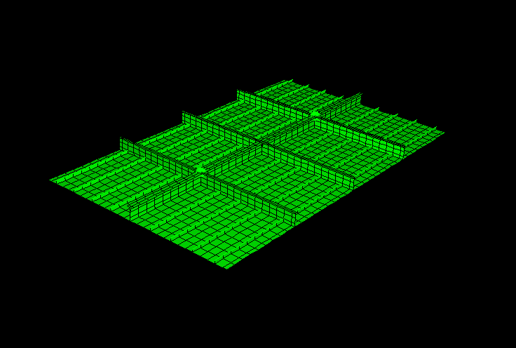
This problem models a reinforced plate structure subjected to in-plane compressive loading that produces localized buckling. Structures are usually designed for service loads properly augmented by safety factors. However, it is quite often of interest to explore their behavior under extreme accident loads. This example looks into a submodel of a naval construction structure. It is a rectangular plate reinforced with beams in its two principal directions (Figure 1.2.5–1). The plate has symmetry boundary conditions along the longer edges and is pinned rigidly along the shorter sides. An in-plane load is applied to one of the pinned sides, compressing the plate. Gravity loads are also applied. The plate buckles under the load. The buckling is initially localized within each of the sections bounded by the reinforcements. At higher load levels the plate experiences global buckling in a row of sections closest to the applied load.
Standard analysis procedures typically provide the load at which the structure starts to buckle. The user may be interested in knowing the structure's additional load carrying capacity. This information could translate, for instance, into knowing when the onset of global buckling takes place or how far into the structure damage propagates. In such situations more sophisticated analysis techniques are necessary. Arc length methods such as the Riks method available in ABAQUS are global load-control methods that are suitable for global buckling and postbuckling analyses; they do not function well when buckling is localized. Alternatives are to analyze the problem dynamically or to introduce damping. In the dynamic case the strain energy released locally from buckling is transformed into kinetic energy; in the damping case this strain energy is dissipated. To solve a quasi-static problem dynamically is typically an expensive proposition. In this example the automatic stabilization capability in ABAQUS, which applies volume proportional damping to the structure, is used.
The model consists of a rectangular plate 10.8 m (425.0 in) long, 6.75 m (265.75 in) wide, and 5.0 mm (0.2 in) thick. This plate has several reinforcements in both the longitudinal and transverse directions (Figure 1.2.5–1). The plate represents part of a larger structure: the two longitudinal sides have symmetry boundary conditions, and the two transverse sides have pinned boundary conditions. In addition, springs at two major reinforcement intersections represent flexible connections to the rest of the structure. The mesh consists of S4 shell elements for both the plate and larger reinforcements and additional S3 shell and B31 beam elements for the remaining reinforcements. The entire structure is made of the same construction steel, with an initial flow stress of 235.0 MPa (34.0 ksi).
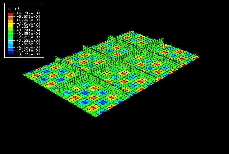
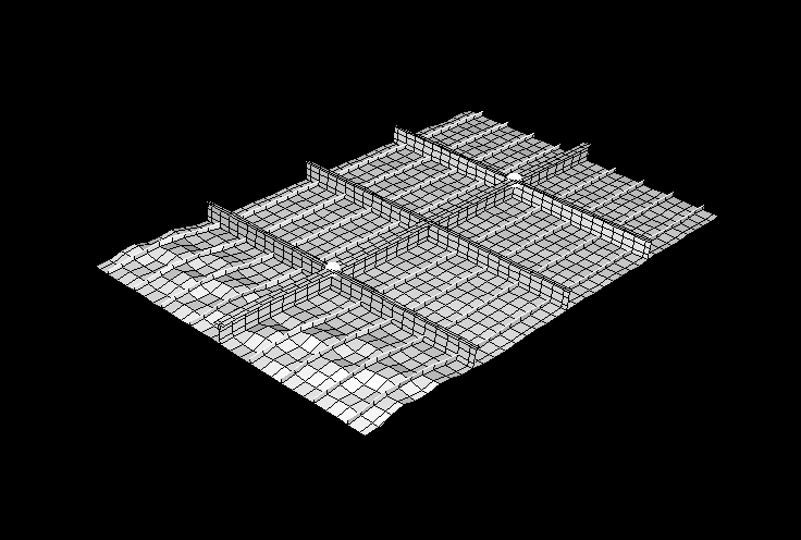
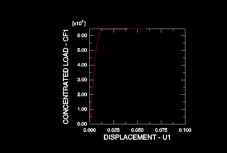
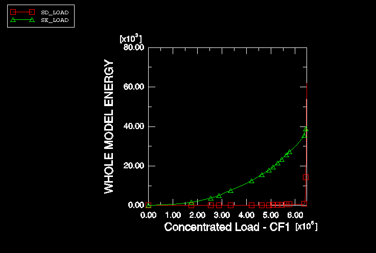
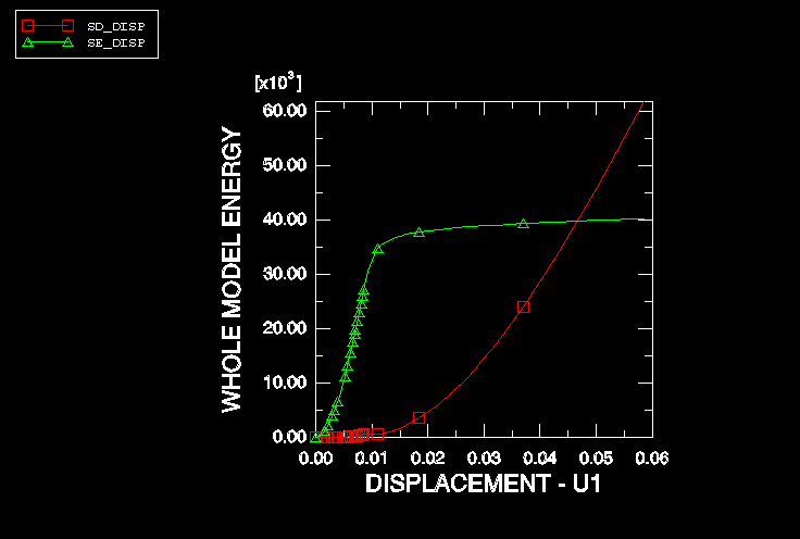
The analysis consists of two steps. In the first step a gravity load perpendicular to the plane of the plate is applied. In the second step a longitudinal compressive load of 6.46 × 10⁶ N (1.45 × 10⁶ lbf) is applied to one of the pinned sides of the plate. All the nodes on that side are forced to move equally by means of multi-point constraints. The analysis is quasi-static, but buckling is expected. The volume proportional damping stabilizing capability in ABAQUS is invoked with the *STATIC, STABILIZE option, with the default damping intensity. This option applies a damping coefficient such that the viscous dissipated energy extrapolated from the first increment to the total step is a small fraction (2.0 × 10⁻⁴) of the strain energy also extrapolated from the first increment to the total step. The algorithm works quite well in situations such as this problem, in which the first increment of a step is stable but instabilities develop later in the analysis. Initially local out-of-plane buckling develops throughout the plate in an almost checkerboard pattern inside each one of the sections delimited by the reinforcements (Figure 1.2.5–2). Later, global buckling develops along a front of sections closer to the applied load (Figure 1.2.5–3). The evolution of the displacements produced by the applied load is very smooth (Figure 1.2.5–4) and does not reflect the early local instabilities in the structure. However, when the global instability develops, the curve becomes almost flat, indicating the complete loss of load carrying capacity. An inspection of the model's energy content (Figure 1.2.5–5 and Figure 1.2.5–6) reveals that while the load is increasing, the amount of dissipated energy is negligible. As soon as the load flattens out, the strain energy also flattens out (indicating a more or less constant load carrying capacity), while the dissipated energy increases dramatically to absorb the work done by the applied loads.
Plate model.
Node definitions for the plate model.
Element definitions for the plate model.