Products: ABAQUS/Standard ABAQUS/Explicit
This example illustrates both a static and dynamic collapse of a steel column constructed by spot welding two channel sections. It is intended to illustrate the modeling of spot welds. “Mesh-independent fasteners,” Section 28.3.4 of the ABAQUS Analysis User's Manual, discusses the mesh-independent spot weld modeling capabilities provided in ABAQUS; while “Breakable bonds,” Section 30.1.9 of the ABAQUS Analysis User's Manual, discusses the use of the *BOND option to model breakable spot welds in ABAQUS/Explicit.
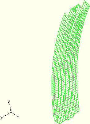
The pillar is composed of two columns of different cross-sections, one box-shaped and the other W-shaped, welded together with spot welds (Figure 1.2.3–1). The top end of the pillar is connected to a rigid body, which makes the deformation of the pillar easy to control by manipulating the rigid body reference node. The box-shaped column is welded to the W-shaped column with five spot welds on either side of the box-shaped column.
The columns are both composed of aluminum-killed steel, which is assumed to satisfy the Ramberg-Osgood relation between true stress and logarithmic strain,
![]()
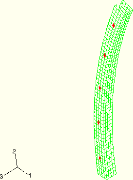
The spot welds are modeled in both ABAQUS/Standard and ABAQUS/Explicit using the mesh-independent fastener capability. Connector elements with CARTESIAN and CARDAN sections are used to define deformable fasteners. The element set containing the connector elements is referenced using the ELSET parameter on the *FASTENER option. The spot welds at nodes 5203, 15203, 25203, 35203, and 45203 are all located on the positive z-side of the box-shaped column, with node 5203 at the bottom end of the column and node 45203 at the top end of the column (see Figure 1.2.3–2). Spot welds at nodes 5211, 15211, 25211, 35211, and 45211 are all located on the negative z-side of the box-shaped column, with node 5211 at the bottom end of the column and node 45211 at the top end of the column. The surfaces of the box-shaped column and the W-shaped column are listed under the *FASTENER option. The spot welds are defined with a diameter of .002 m. The deformable behavior in the fastener is modeled using connector elasticity, with an elastic spring stiffness of 2.0 GPa in translational as well as rotational components. For the ABAQUS/Explicit analysis spot weld damage and failure are modeled using connector damage behavior. A force-based coupled damage initiation criterion that uses a connector potential with both connector force and connector moment ingredients is used. (For further description of the connector potential used, see the spot weld example in “Connector functions for coupled behavior,” Section 25.2.4 of the ABAQUS Analysis User's Manual.) Damage initiates when the value of the potential exceeds 2 × 10⁵ N. A post-damage-initiation equivalent displacement of 1 × 10⁻⁷ m is allowed. Once the post-damage-initiation equivalent displacement in a spot weld reaches this value, the spot weld ceases to carry any load. Both the continuum and structural coupling capabilities are used to define the fasteners.
To study spot weld failure and the post-yield behavior of the spot welds in detail, the problem is also solved using the *BOND option available in ABAQUS/Explicit. The column with the box-shaped cross-section is defined to be the slave surface in contact with the column with the W-shaped cross-section. The spot welds on the two sides of the box-shaped column are modeled with different yield forces and post-yield behavior to illustrate the two failure models. For the spot-welded nodes 5203, 15203, 25203, 35203, and 45203, the force to cause failure for the spot welds is 3000 N in pure tension and 1800 N in pure shear. Once the spot welds start to fail, the maximum force that they can bear is assumed to decay linearly with time over the course of 2.0 msec, which illustrates the modeling of complete loss of strength over a given time period. For the spot-welded nodes 5211, 15211, 25211, 35211, and 45211, the force to cause failure for these spot welds is 4000 N in pure tension and 2300 N in pure shear. These spot welds fail according to the damaged failure model, which assumes that the maximum forces that the spot welds can carry decay linearly with relative displacement between the welded node and the master surface. The welds are defined to fail completely once their total relative displacement reaches 0.3 mm, which illustrates the modeling of loss of strength in the spot welds based on energy absorption.
The bottom of the pillar is fully fixed. In the ABAQUS/Standard analysis the reference node for the rigid body at the top of the pillar moves 0.25 m in the y-direction, thus loading it in compression, together with a displacement of .02 m in the z-direction that shears it slightly. At the same time the end of the pillar is rotated about the negative z-axis by 0.785 rad and rotated about the negative x-axis by 0.07 rad.
In the ABAQUS/Explicit analyses the reference node for the rigid body at the top of the pillar moves at a constant velocity of 25 m/sec in the y-direction, thus loading it in compression, together with a velocity of 2 m/sec in the z-direction that shears it slightly. At the same time the end of the pillar is rotated about the negative z-axis at 78.5 rad/sec and rotated about the negative x-axis at 7 rad/sec. This loading is applied by prescribing the velocities of the rigid body reference node that is attached to the top end of the compound pillar.
The analysis is carried out over 10 milliseconds.
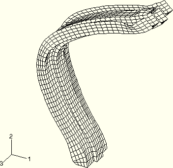
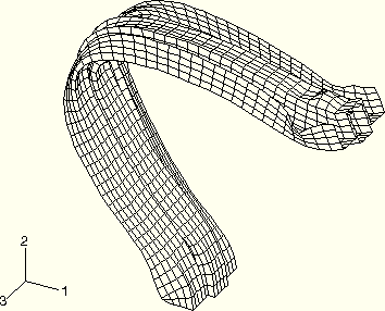
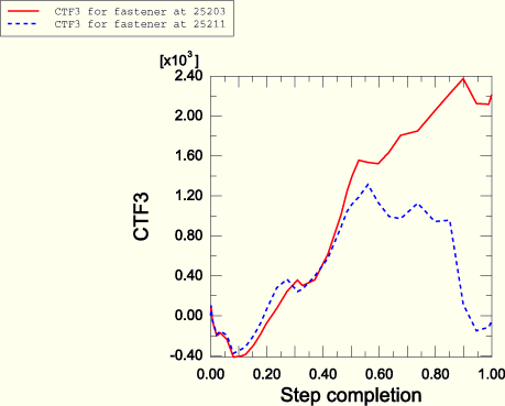
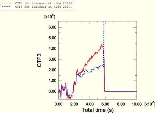
The mesh-independent spot weld capability and the contact-based spot weld capability predict very similar deformation patterns and deformed shapes for the pillar. Figure 1.2.3–3 shows the deformed shape of the pillar after 5.0 msec in the ABAQUS/Explicit analysis. Figure 1.2.3–4 shows the deformed shape of the pillar after 10.0 msec. The spot welds in the mesh-independent ABAQUS/Explicit analysis undergo damage and fail. For the current choice of parameters for the connector damage model, it is found that damage initiates in the spot welds at nodes 15203 through 45203 on the positive side of the box-shaped column and at nodes 15211 through 45211 on the negative side of the box-shaped column. However, the post-damage-initiation displacement is sufficient to cause ultimate failure of the spot welds at nodes 15203, 25203, 15211, and 25211 only. Figure 1.2.3–9 illustrates the undamaged connector force CTF3 in the spot welds associated with reference nodes 25203 and 25211 as computed in the ABAQUS/Standard analyses. Figure 1.2.3–10 illustrates the damaged connector force CTF3 in the spot welds associated with reference nodes 25203 and 25211 as computed in the ABAQUS/Explicit analyses. Forces in both spot welds drop to zero when ultimate failure occurs in the ABAQUS/Explicit analyses.
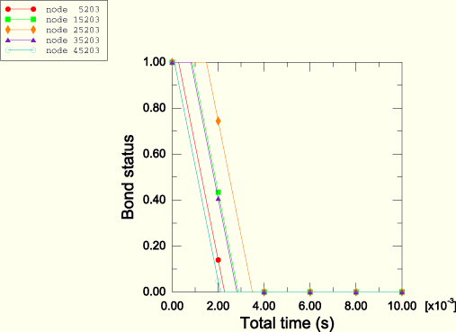
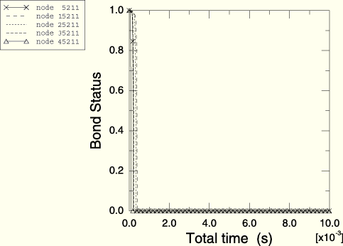
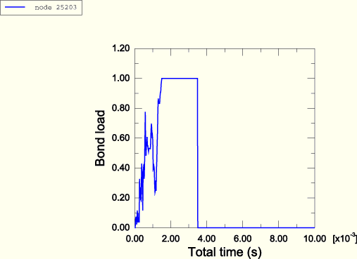
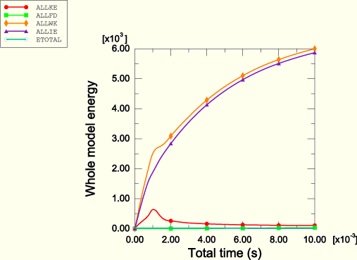
The failure and post-yield behaviors of the pillar are also studied using the contact-based spot weld capability. Figure 1.2.3–5 and Figure 1.2.3–6 show the status of the spot welds on the positive z-side of the column and the negative z-side of the column, respectively. In these figures a status of 1.0 means that the weld is fully intact, and a status of 0.0 means that the weld has failed completely. Figure 1.2.3–7 shows the load on spot weld node 25203 relative to the failure load. This relative value is called the bond load and is defined to be 1.0 when the spot weld starts to fail and 0.0 when the spot weld is broken. Figures showing the bond status and bond load may not match the analysis results on a particular platform. This is due to the fact that contact forces in this analysis show significant noise, which can vary across platforms. When the time-to-failure model is used, spot weld behavior is very sensitive to any spike in the bond force that reaches the bond strength. Spot weld behavior is less sensitive to individual spikes in the bond force when the damaged failure model is used. Figure 1.2.3–8 shows the time history of the total kinetic energy, the total work done on the model, the total energy dissipated by friction, the total internal energy, and the total energy balance.
Input data for the ABAQUS/Explicit mesh-independent spot weld analysis.
Input data for the ABAQUS/Explicit mesh-independent spot weld analysis using structural coupling in the fastener definitions.
Input data for the ABAQUS/Standard mesh-independent spot weld analysis.
Input data for the ABAQUS/Standard mesh-independent spot weld analysis using structural coupling in the fastener definitions.
Input data for the ABAQUS/Standard mesh-independent spot weld analysis using small-sliding contact with shell thickness taken into account.
Input data for the contact-pair-based spot weld analysis.
Input data for the general-contact-based spot weld analysis.
Input data used to test the restart capability with spot welds.
Analysis using the double-sided surface capability.