Products: ABAQUS/Standard ABAQUS/Explicit
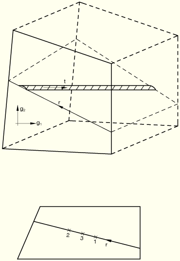
Let ![]() be the element's usual isoparametric coordinates. Let
be the element's usual isoparametric coordinates. Let ![]() be an isoparametric coordinate along the line where the face of the element intersects the plane of reinforcement, with
be an isoparametric coordinate along the line where the face of the element intersects the plane of reinforcement, with ![]() in an element (see Figure 3.7.1–1).
in an element (see Figure 3.7.1–1).
The rebar will be integrated at one or two points, depending on the order of interpolation in underlying elements. The volume of integration ![]() , position, rebar strain
, position, rebar strain ![]() , and first and second variations of rebar strain
, and first and second variations of rebar strain ![]() and
and ![]() at each point are calculated as
at each point are calculated as
![]()
![]()
is the original thickness for plane elements and ![]() for axisymmetric elements;
for axisymmetric elements;
![]()
is the rebar cross-sectional area;
![]()
is the spacing of rebar (for axisymmetric elements ![]() , where
, where ![]() is the radius where the spacing
is the radius where the spacing ![]() is given);
is given);
![]()
is the Gauss weight associated with the integration point along the ![]() line;
line;
![]()
is position; and
![]()
Strain is
![]()
For the deformations allowed in these elements,
![]()
![]()
![]()
for plane stress or plane strain;
![]()
for generalized plane strain, where ![]() is given in “Generalized plane strain elements,” Section 3.2.7; and
is given in “Generalized plane strain elements,” Section 3.2.7; and
![]()
for axisymmetric elements.
From these results the first variation of strain is
![]()
![]()
for plane stress and plane strain,
![]()
for generalized plane strain, and
![]()
for axisymmetric cases.