Product: ABAQUS/Standard
Element type STRI3 in ABAQUS/Standard is a facet shell—a plate element used to approximate a shell. The element has three nodes, each with six degrees of freedom. The strains are based on thin plate theory, using a small-strain approximation. Arbitrary rigid body rotations are accounted for exactly by formulating the deformation of the element in a local coordinate system that rotates with the element. The element also satisfies the patch test, so that it will produce reliable results with appropriate meshes.
The bending of the element is based on a discrete Kirchhoff approach to plate bending, using Batoz's interpolation functions (Batoz et al., 1980). This formulation satisfies the Kirchhoff constraints all around the boundary of the triangle and provides linear variation of curvature throughout the element. However, the membrane strains are assumed constant within the element. In addition, a curved shell is approximated by this element as a set of facets formed by the planes defined by the three nodes of each element. For these reasons it is necessary to use a reasonably well refined mesh in most applications.
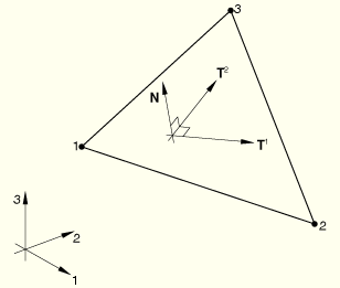
A local orthonormal basis system, ![]() and
and ![]() , is defined in the plane of each element in the reference configuration, using the standard ABAQUS convention.
, is defined in the plane of each element in the reference configuration, using the standard ABAQUS convention. ![]() and
and ![]() measure distance along
measure distance along ![]() and
and ![]() in the reference configuration.
in the reference configuration.
![]()
![]()
![]()
Here ![]() and
and ![]() are the spatial coordinates of a point in the current and reference configurations, respectively. Curvature changes are defined incrementally. To account for large rigid body rotations we use a local coordinate system that rotates with the plane defined by the three nodes of the element. The basis vectors chosen for this local system are
are the spatial coordinates of a point in the current and reference configurations, respectively. Curvature changes are defined incrementally. To account for large rigid body rotations we use a local coordinate system that rotates with the plane defined by the three nodes of the element. The basis vectors chosen for this local system are ![]() and
and ![]() . Since the membrane strains are assumed to be small, these vectors will be approximately orthonormal. The components of incremental rotation of the normal to the plate are defined as
. Since the membrane strains are assumed to be small, these vectors will be approximately orthonormal. The components of incremental rotation of the normal to the plate are defined as ![]() about
about ![]() and
and ![]() about
about ![]() . The incremental displacement of the reference surface of the plate along the normal to the plane of its nodes is defined as
. The incremental displacement of the reference surface of the plate along the normal to the plane of its nodes is defined as ![]() . (Note that
. (Note that ![]() will be zero at the nodes at all times because the plane containing
will be zero at the nodes at all times because the plane containing ![]() and
and ![]() always passes through the nodes.) The Kirchhoff constraints are, approximately,
always passes through the nodes.) The Kirchhoff constraints are, approximately,
![]()
![]()
Batoz (1980) assumes that ![]() and
and ![]() vary quadratically over the element and that
vary quadratically over the element and that ![]() is defined independently along each of the three sides of the element as a cubic function. The Kirchhoff constraints are then imposed at the corners and at the middle of each element edge along the direction of the edge to give
is defined independently along each of the three sides of the element as a cubic function. The Kirchhoff constraints are then imposed at the corners and at the middle of each element edge along the direction of the edge to give
![]()
![]()
![]()
In the above expressions ![]() and
and ![]() are interpolation functions that are defined by Batoz (1980), and the incremental rotation components at the nodes,
are interpolation functions that are defined by Batoz (1980), and the incremental rotation components at the nodes, ![]() , are defined as
, are defined as
![]()
![]()
The three membrane strains and three curvature strains complete the basic kinematic description of the element, except that the use of six degrees of freedom per node introduces a spurious rotation at each node (only two incremental rotations at each node appear in the above equations—the rotation about the normal to the plane of the element's nodes does not enter). To deal with this problem, we define a generalized strain to be penalized with a small stiffness at each node as
![]()
The first variations of strain are
![]()
![]()
Also, for the “strain” used to introduce the extra stiffness at the nodes to avoid singularity caused by the component of rotation about the normal,
![]()
The second variations of strain are
![]()
The internal virtual work rate is defined as
The formulation now proceeds as for the shell elements described in “Shear flexible small-strain shell elements,” Section 3.6.3, using a 3-point integration scheme in the plane of the element.