Products: ABAQUS/Standard ABAQUS/Explicit
The library of solid elements in ABAQUS includes first- and second-order triangles, tetrahedra, and wedge elements for planar, axisymmetric, and three-dimensional analysis.
Hybrid versions of these elements are provided for use with incompressible and nearly incompressible constitutive models (see “Hybrid incompressible solid element formulation,” Section 3.2.3, for a detailed discussion of the formulation used). However, these hybrid forms should be used only to fill in regions in meshes made of brick elements; otherwise, too many constraint variables may be introduced.
Second-order tetrahedra are not suitable for the analysis of contact problems: a constant pressure on an element face produces zero equivalent loads at the corner nodes. In contact problems this makes the contact condition at the corners indeterminate, with failure of the solution likely because of excessive gap chatter. The same argument holds true for contact on triangular faces of a wedge element.

The interpolation is defined in terms of the element coordinates ![]() ,
, ![]() , and
, and ![]() shown in Figure 3.2.6–1. Since ABAQUS is a Lagrangian code for most applications, these are also material coordinates. They each span a range from 0 to 1 in an element but satisfy the constraint that
shown in Figure 3.2.6–1. Since ABAQUS is a Lagrangian code for most applications, these are also material coordinates. They each span a range from 0 to 1 in an element but satisfy the constraint that ![]() for triangles and wedges and
for triangles and wedges and ![]() for tetrahedra. The node numbering convention used in ABAQUS for these elements is also shown in Figure 3.2.6–1. Corner nodes are numbered first, and then the midside nodes for second-order elements. The interpolation functions are as follows.
for tetrahedra. The node numbering convention used in ABAQUS for these elements is also shown in Figure 3.2.6–1. Corner nodes are numbered first, and then the midside nodes for second-order elements. The interpolation functions are as follows.
First-order triangle (3 nodes):
![]()
Second-order triangle (6 nodes):

First-order tetrahedron (4 nodes):
![]()
Second-order tetrahedron (10 nodes):

First-order wedge (6 nodes):

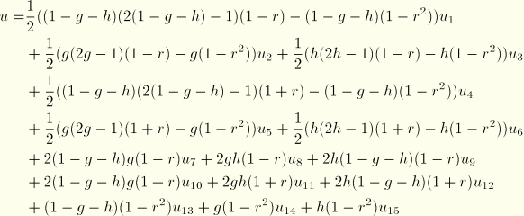
Second-order wedge (15 nodes):

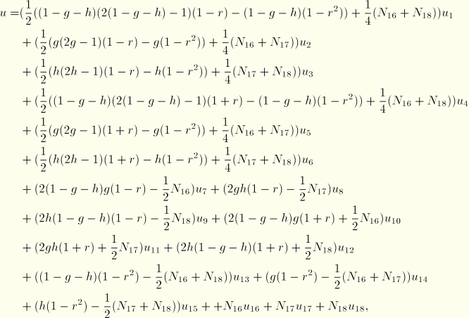
Second-order variable 15–18 node wedge (assuming all 18 nodes are defined):

![]()
![]()
![]()

The first-order triangle and tetrahedron are constant stress elements and use a single integration point for the stiffness calculation when used in stress/displacement applications. A lumped mass matrix is used for both elements, with the total mass divided equally over the nodes. For heat transfer applications a three-point integration scheme is used for the conductivity and heat capacity matrices of the first-order triangle, with the integration points midway between the vertices and the centroid of the element; and a four-point integration scheme is used for the first-order tetrahedron. Distributed loads are integrated with two and three points for first-order triangles and tetrahedrons, respectively.
The three-point scheme is also used for the stiffness of the second-order triangle when it is used in stress/displacement applications. The mass matrix is integrated with a six-point scheme that integrates fourth-order polynomials exactly (Cowper, 1973). Distributed loads are integrated using three points. The heat transfer versions of the element use the six-point scheme for the conductivity and heat capacity matrices.
For stress/displacement applications the second-order tetrahedron uses 4 integration points for its stiffness matrix and 15 integration points for its consistent mass matrix. For heat transfer applications the conductivity and heat capacity matrices are integrated using 15 integration points. The first-order wedge uses 2 integration points for its stiffness matrix but 6 integration points for its lumped mass matrix. The second-order wedge uses 9 integration points for its stiffness matrix but 18 integration points for its consistent mass matrix. The integration schemes used for the second-order tetrahedra and wedge elements can be found in Stroud (1971).