Product: ABAQUS/Standard
The lower-order quadrilateral continuum elements in ABAQUS/Standard of type CPS4I, CPE4I, CAX4I, CPEG4I, and C3D8I as well as the related hybrid, coupled temperature-displacement and pore pressure elements are enhanced by incompatible modes to improve the bending behavior. In addition to the displacement degrees of freedom, incompatible deformation modes are added internal to the elements. The primary effect of these degrees of freedom is to eliminate the so-called parasitic shear stresses that are observed in regular displacement elements if they are loaded in bending.
In addition, these degrees of freedom eliminate artificial stiffening due to Poisson's effect in bending. In regular displacement elements the linear variation of the axial stress due to bending is accompanied by a linear variation of the stress perpendicular to the bending direction, which leads to incorrect stresses and an overestimation of the stiffness. The incompatible modes prevent such a stress from occurring.
In the nonhybrid elements (except CPS4I) additional incompatible modes are added to prevent locking of the elements for approximately incompressible material behavior. For fully incompressible material behavior, hybrid elements must be used. In these elements pressure degrees of freedom are added to enforce a linear pressure variation inside the element. In the hybrid elements the additional incompatible modes used to prevent locking are not included.
The incompatible mode elements perform almost as well as second-order elements in many situations if the elements have an approximately rectangular shape. The performance is considerably less if the elements have a parallelogram shape. For trapezoidal element shapes the performance is not much better than the performance of regular displacement elements.
Because of the internal degrees of freedom (4 for CPS4I; 5 for CPE4I, CAX4I, and CPEG4I; and 13 for C3D8I) the elements are somewhat more expensive than regular displacement elements. However, the additional degrees of freedom do not substantially increase the wavefront size since they can be eliminated immediately. In addition, it is not necessary to use selectively reduced integration, which partially offsets the cost of the additional degrees of freedom.
The geometrically linear incompatible mode formulation used in ABAQUS is related to the work presented by Simo and Rifai (1990). Simo's formulation is very similar to much earlier work done by Wilson et al. (1973) and Taylor et al. (1976). The nonlinear formulation is based on work by Simo and Armero (1992).

As discussed in the paper by Simo, the incompatible mode formulation can be derived in a rigorous way from the general Hu-Washizu variational principle. In this discussion we will not present this derivation but use only the key results of Simo's work.
In the incompatible mode formulation, the displacement gradient ![]() is augmented with an additional, incompatible displacement gradient field
is augmented with an additional, incompatible displacement gradient field ![]() :
:
![]()
![]()
![]()
The last condition is used to obtain a suitable general form of the incompatible modes. We describe the incompatible field as a transformation of a parametric gradient field ![]() :
:
![]()
![]()
![]()
![]()

For two-dimensional elements this yields
![]()
![]()
![]()
![]()

![]()
With the addition of these terms, parasitic shear and Poisson's effect in bending are eliminated. Note that the vectors ![]() in
in ![]() appear in a similar form as the nodal displacement vectors
appear in a similar form as the nodal displacement vectors ![]() in
in ![]() ,
,
![]()
For approximately incompressible material behavior, bilinear patterns in the hydrostatic stress can still be observed in all elements except CPS4I. These patterns can be eliminated by the introduction of additional incompatible modes of the form
![]()
![]()
![]()
![]()
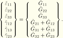
The symmetric part of the incompatible displacement gradient contributes to incompatible strains:


Since we want to use a formulation that can be used for any material model, we want to express the incompatible modes as a modification of the deformation gradient ![]() . The most obvious approach is to add the incompatible modes to the deformation gradient:
. The most obvious approach is to add the incompatible modes to the deformation gradient:
Satisfaction of the instantaneous patch test requires the addition of an incompatible deformation rate tensor to the standard rate of deformation:
![]()
![]()
![]()
Similar to Equation 3.2.5–2 the principal incompatible modes are described as a transformation of the parametric gradient field ![]() :
:
![]()
The incremental parametric gradient field ![]() has exactly the same form as in the linear formulation,
has exactly the same form as in the linear formulation,
![]()
![]()
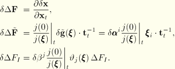
The variation in the gradient of the position with respect to the current state is obtained from the fundamental relation


This allows us to write for ![]()
![]()


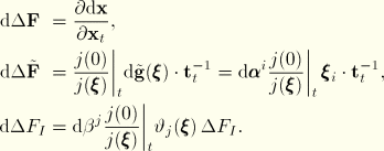
For a finite-strain increment we use the midincrement approach proposed by Hughes and Winget. This yields
![]()
![]()
The additional bilinear modes appear in the first variation only as variations (the values ![]() themselves do not appear); hence, the contributions to the second variation can be neglected.
themselves do not appear); hence, the contributions to the second variation can be neglected.