Products: ABAQUS/Standard ABAQUS/Explicit
This problem examines the use of the smeared crack model (“Concrete smeared cracking,” Section 11.5.1 of the ABAQUS Analysis User's Manual) and the brittle cracking model (“Cracking model for concrete,” Section 11.5.2 of the ABAQUS Analysis User's Manual) for the analysis of reinforced concrete structures. The geometry of the problem is defined in Figure 1.1.5–1. A square slab is supported in the transverse direction at its four corners and loaded by a point load at its center. The slab is reinforced in two directions at 75% of its depth. The reinforcement ratio (volume of steel/volume of concrete) is 8.5 × 10⁻³ in each direction. The slab was tested experimentally by McNeice (1967) and has been analyzed by a number of workers, including Hand et al. (1973), Lin and Scordelis (1975), Gilbert and Warner (1978), Hinton et al. (1981), and Crisfield (1982).

Symmetry conditions allow us to model one-quarter of the slab. A 3 × 3 mesh of 8-node shell elements is used for the ABAQUS/Standard analysis. No mesh convergence studies have been performed, but the reasonable agreement between the analysis results and the experimental data suggests that the mesh is adequate to predict overall response parameters with usable accuracy. Three different meshes are used in ABAQUS/Explicit to assess the sensitivity of the results to mesh refinement: a coarse 6 × 6 mesh, a medium 12 × 12 mesh, and a fine 24 × 24 mesh of S4R elements. Nine integration points are used through the thickness of the concrete to ensure that the development of plasticity and failure is modeled adequately. The two-way reinforcement is modeled using the *REBAR LAYER option. Symmetry boundary conditions are applied on the two edges of the mesh, and the corner point is restrained in the transverse direction.

The material data are given in Table 1.1.5–1. The material properties of concrete are taken from Gilbert and Warner (1978). Some of these data are assumed values, because they are not available for the concrete used in the experiment. The assumed values are taken from typical concrete data. The compressive behavior of concrete in the cracking model in ABAQUS/Explicit is assumed to be linear elastic. This is a reasonable assumption for a case such as this problem, where the behavior of the structure is dominated by cracking resulting from tension in the slab under bending.
The modeling of the concrete-reinforcement interaction and the energy release at cracking is of critical importance to the response of a structure such as this once the concrete starts to crack. These effects are modeled in an indirect way by adding “tension stiffening” to the plain concrete model. This approach is described in “A cracking model for concrete and other brittle materials,” Section 4.5.3 of the ABAQUS Theory Manual; “Concrete smeared cracking,” Section 11.5.1 of the ABAQUS Analysis User's Manual; and “Cracking model for concrete,” Section 11.5.2 of the ABAQUS Analysis User's Manual. The simplest tension stiffening model defines a linear loss of strength beyond the cracking failure of the concrete. In this example three different values for the strain beyond failure at which all strength is lost (5 × 10⁻⁴, 1 × 10⁻³, and 2 × 10⁻³) are used to illustrate the effect of the tension stiffening parameters on the response.
Since the response is dominated by bending, it is controlled by the material behavior normal to the crack planes. The material's shear behavior in the plane of the cracks is not important. Consequently, the choice of shear retention has no significant influence on the results. In ABAQUS/Explicit the shear retention chosen is exhausted at the same value of the crack opening at which tension stiffening is exhausted. In ABAQUS/Standard full shear retention is used because it provides a more efficient numerical solution.

Since considerable nonlinearity is expected in the response, including the possibility of unstable regimes as the concrete cracks, the modified Riks method is used with automatic incrementation in the ABAQUS/Standard analysis. With the Riks method the load data and solution parameters serve only to give an estimate of the initial increment of load. In this case it seems reasonable to apply an initial load of 1112 N (250 lb) to the quarter-model for a total initial load on the structure of 4448 N (1000 lb). This can be accomplished by specifying a load of 22241 N (5000 lb) and an initial time increment of 0.05 out of a total time period of 1.0. The analysis is terminated when the central displacement reaches 25.4 mm (1 in).
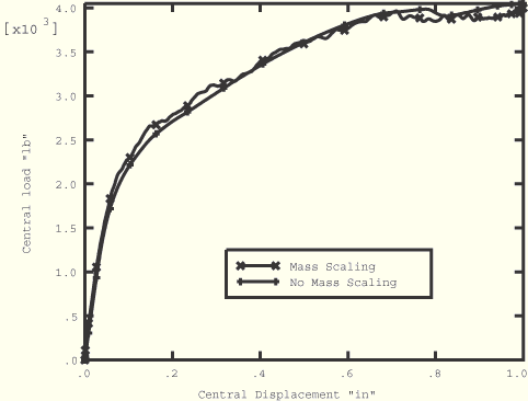
Since ABAQUS/Explicit is a dynamic analysis program and in this case we are interested in static solutions, the slab must be loaded slowly enough to eliminate any significant inertia effects. The slab is loaded in its center by applying a velocity that increases linearly from 0 to 2.0 in/second such that the center displaces a total of 1 inches in 1 second. This very slow loading rate ensures quasi-static solutions; however, it is computationally expensive. The CPU time required for this analysis can be reduced in one of two ways: the loading rate can be increased incrementally until it is judged that any further increase in loading rate would no longer result in a quasi-static solution, or mass scaling can be used (see “Explicit dynamic analysis,” Section 6.3.3 of the ABAQUS Analysis User's Manual). These two approaches are equivalent. Mass scaling is used here to demonstrate the validity of such an approach when it is used in conjunction with the brittle cracking model. Mass scaling is done by increasing the density of the concrete and the reinforcement by a factor of 100, thereby increasing the stable time increment for the analysis by a factor of 10 and reducing the computation time by the same amount while using the original slow loading rate. Figure 1.1.5–4 shows the load-deflection response of the slab for analyses using the 12 × 12 mesh with and without mass scaling. The mass scaling used does not affect the results significantly; therefore, all subsequent analyses are performed using mass scaling.
Results for each analysis are discussed in the following sections.
The numerical and experimental results are compared in Figure 1.1.5–2 on the basis of load versus deflection at the center of the slab. The strong effect of the tension stiffening assumption is very clear in that plot. The analysis with tension stiffening, such that the tensile strength is lost at a strain of 10–3 beyond failure, shows the best agreement with the experiment. This analysis provides useful information from a design viewpoint. The failure pattern in the concrete is illustrated in Figure 1.1.5–3, which shows the predicted crack pattern on the lower surface of the slab at a central deflection of 7.6 mm (0.3 in).
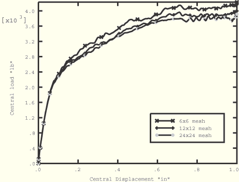
Figure 1.1.5–5 shows the load-deflection response of the slab for the three different mesh densities using a tension stiffening value of 2 × 10⁻³. Since the coarse mesh predicts a slightly higher limit load than the medium and fine meshes do and the limit loads for the medium and fine mesh analyses are very close, the tension stiffening study is performed using the medium mesh only.
The numerical (12 × 12 mesh) results are compared to the experimental results in Figure 1.1.5–6 for the three different values of tension stiffening. It is clear that the less tension stiffening used, the softer the load-deflection response is. A value of tension stiffening somewhere between the highest and middle values appears to match the experimental results best. The lowest tension stiffening value causes more sudden cracking in the concrete and, as a result, the response tends to be more dynamic than that obtained with the higher tension stiffening values.
Figure 1.1.5–7 shows the numerically predicted crack pattern on the lower surface of the slab for the medium mesh.
S8R elements.
S9R5 elements.
Coarse (6 × 6) mesh; tension stiffening = 2 × 10⁻³.
Medium (12 × 12) mesh; tension stiffening = 2 × 10⁻³.
Fine (24 × 24) mesh; tension stiffening = 2 × 10⁻³.
Medium (12 × 12) mesh; tension stiffening = 1 × 10⁻³.
Medium (12 × 12) mesh; tension stiffening = 5 × 10⁻⁴.
Medium (12 × 12) mesh; tension stiffening = 2 × 10⁻³; no mass scaling.

Crisfield, M. A., “Variable Step-Length for Nonlinear Structural Analysis,” Report 1049, Transport and Road Research Lab., Crowthorne, England, 1982.
Gilbert, R. I., and R. F. Warner, “Tension Stiffening in Reinforced Concrete Slabs,” Journal of the Structural Division, American Society of Civil Engineers, vol. 104, ST12, pp. 1885–1900, 1978.
Hand, F. D., D. A. Pecknold, and W. C. Schnobrich, “Nonlinear Analysis of Reinforced Concrete Plates and Shells,” Journal of the Structural Division, American Society of Civil Engineers, vol. 99, ST7, pp. 1491–1505, 1973.
Hinton, E., H. H. Abdel Rahman, and O. C. Zienkiewicz, “Computational Strategies for Reinforced Concrete Slab Systems,” International Association of Bridge and Structural Engineering Colloquium on Advanced Mechanics of Reinforced Concrete, pp. 303–313, 1981.
Lin, C. S., and A. C. Scordelis, “Nonlinear Analysis of Reinforced Concrete Shells of General Form,” Journal of the Structural Division, American Society of Civil Engineers, vol. 101, pp. 523–238, 1975.
McNeice, A. M., “Elastic-Plastic Bending of Plates and Slabs by the Finite Element Method,” Ph. D. Thesis, London University, 1967.

Table 1.1.5–1 Material properties for the McNeice slab.
| Concrete properties: | |
| Properties are taken from Gilbert and Warner (1978) if available in that paper. | |
| Properties marked with a * are not available and are assumed values. | |
| Young's modulus | 28.6 GPa (4.15 × 10⁶ lb/in2) |
| Poisson's ratio | 0.15 |
| Uniaxial compression values: | |
| Yield stress | 20.68 MPa (3000 lb/in2)* |
| Failure stress | 37.92 MPa (5500 lb/in2) |
| Plastic strain at failure | 1.5 × 10⁻³* |
| Ratio of uniaxial tension | |
| to compression failure stress | 8.36 × 10⁻² |
| Ratio of biaxial to uniaxial | |
| compression failure stress | 1.16* |
| Cracking failure stress | 459.8 lb/in2 (3.17 MPa) |
| Density (before mass scaling) | 2.246 × 10⁻⁴ lb s2/in4 (2400 kg/m3) |
| “Tension stiffening” is assumed as a linear decrease of the stress to zero stress, at a strain of 5 × 10⁻⁴, at a strain of 10 × 10–4, or at a strain of 20 × 10–4. | |
| Steel (rebar) properties: | |
| Young's modulus | 200 GPa (29 × 106 lb/in2) |
| Yield stress | 345 MPa (50 × 103 lb/in2) |
| Density (before mass scaling) | 7.3 × 10⁻⁴ lb s2/in4 (7800 kg/m3) |

Figure 1.1.5–4 Load-deflection response of McNeice slab, ABAQUS/Explicit; influence of mass scaling.

Figure 1.1.5–5 Load-deflection response of McNeice slab, ABAQUS/Explicit; influence of mesh refinement.
