Computer Architecture
Section 4 Solutions:
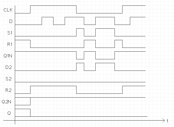
- 1. The D type flip-flop shown below is made of D type latches. Finish
the timing diagram for the given input signals.

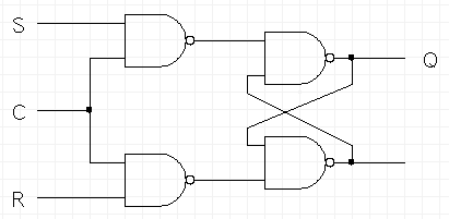
- 2. In class and the book we used NOR gates to build a latch. Design
a level sensitive SR latch using NAND gates.
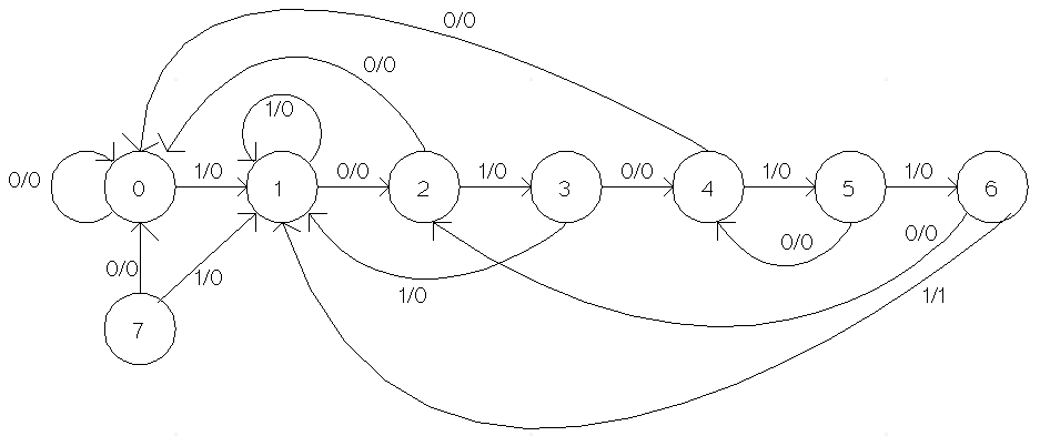
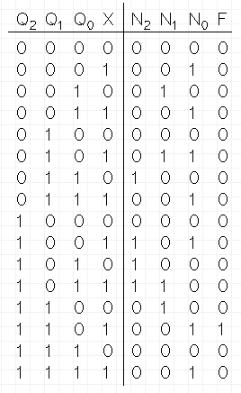
- 3. Use the design process to design a Mealy model circuit that
detects the bit pattern 1110101 (least significant bit first). The
pattern can overlap. The output detection signal goes high when the
pattern is detected, 0 otherwise. Show a state diagram and state
table.
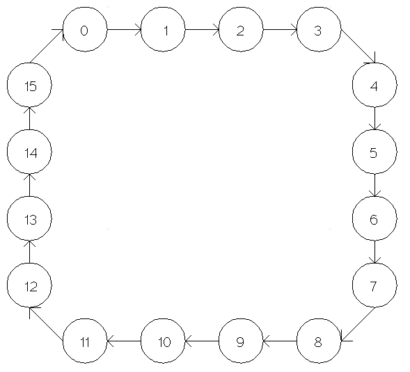
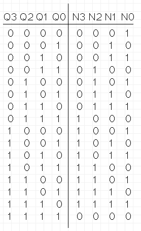
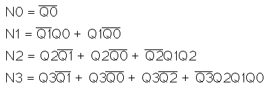
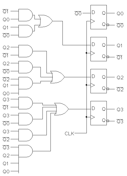
- 4. Using the design process, design a 4-bit counter. There are no
input signals and the only output signals are the current state
signals.
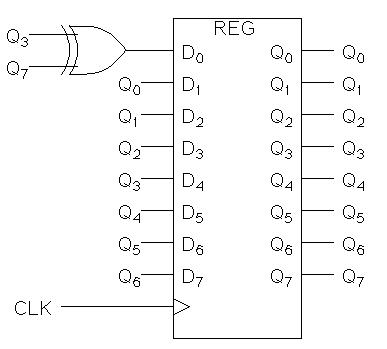
- 5. For the circuit given below, determine the output, Q,
for 12 clock cycles starting with Q = 00110111.
| Time |
Q7 |
Q6 |
Q5 |
Q4 |
Q3 |
Q2 |
Q1 |
Q0 |
| T0 |
0 |
0 |
1 |
1 |
0 |
1 |
1 |
1 |
| T1 |
0 |
1 |
1 |
0 |
1 |
1 |
1 |
0 |
| T2 |
1 |
1 |
0 |
1 |
1 |
1 |
0 |
1 |
| T3 |
1 |
0 |
1 |
1 |
1 |
0 |
1 |
0 |
| T4 |
0 |
1 |
1 |
1 |
0 |
1 |
0 |
0 |
| T5 |
1 |
1 |
1 |
0 |
1 |
0 |
0 |
0 |
| T6 |
1 |
1 |
0 |
1 |
0 |
0 |
0 |
0 |
| T7 |
1 |
0 |
1 |
0 |
0 |
0 |
0 |
1 |
| T8 |
0 |
1 |
0 |
0 |
0 |
0 |
1 |
1 |
| T9 |
1 |
0 |
0 |
0 |
0 |
1 |
1 |
0 |
| T10 |
0 |
0 |
0 |
0 |
1 |
1 |
0 |
1 |
| T11 |
0 |
0 |
0 |
1 |
1 |
0 |
1 |
1 |
| T12 |
0 |
0 |
1 |
1 |
0 |
1 |
1 |
1 |


