Temperature Sensor (TMP102 x2) + Arduino Mega
Since the each circuit for each heating pad was identical, we initially stuck to working with and debugging one, knowing ti wold be the same for the second pad. However, something we learned along the way is that connecting multiple TMP102 sensors to an Arduino Mega board required some extra work. This is how we had to do it.
Materials: Arduino Mega board, two TMP102 sensors (found here), wires (it helps to solder them to the sensor leads first)
Step 1: Start with one TMP102 sensor. We followed the TMP102 Breakout Guide found on Sparkfun’s website on an Arduino Uno board, and it worked like a charm. Do this to familiarize yourself, and make sure to download the “SparkfunTMP102.h” library and import it into your Arduino (“Sketch” -> “Include Library” -> “Add .ZIP Library”) before copying and pasting the code.
- Notice how only 5 of the 6 pins of the sensor are connected. The 6th one is the ADD0 pin, which essentially sets the address of the sensor. The default address is already embedded as (0x48), so your first sensor does not need this. This pin will be used in the second (and any subsequent) TMP102 sensors.
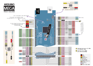
Issues arose when trying to transfer what he had just done onto an Arduino Mega board, since the library is designed for specifically Arduino Uno boards. Nathan was instrumental in helping us with this, but the process is actually not too difficult. It first starts with observing the pinout diagram for an Arduino Mega board.
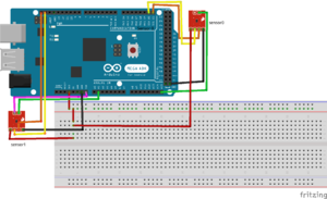
Step 2: Construct the new circuit diagram as shown. Leave the first TMP102 as it was connected previously, except this time, connect the “3V3” pin from the Arduino Mega onto a breadboard, as both sensors need this and there is only one of these pins on the board. Then use this code
- The rest of the connections are easy. There are enough “GND,” “SCL,” (orange wires) and “SDA,” (yellow wires) pins on the Arduino Mega for the sensor to fit, as well as a ton of Analog pins (green wires) for the “ALT” (Alert) leads.
- Note the pink wire on the second sensor. This is the ADD0 pin, and it needs to be connected to a pin on the board and its address needs to changed from (0x48) in the code, which can be found [here]
- The specific pin to connect to is the “VIN” pin, and in the code, you need to initialize it (before the void setup code) as “TMP102 sensor1(0x49)”.
Step 3: Aside from that initialization, the rest of the mimics the code found on the Sparkfun website in Step 1. You should now see printed temperature values and alert states for both sensor, simultaneously!


