Spectrum Shield (Sparkfun) + Arduino
The spectrum shield for Arduino, combined with specific code allows one to separate a processed or raw audio signal into seven bands of frequency. It takes in either an analog sound input by soldering the input to the left, right, and ground visible on the board, or from the built in 1/8” auxiliary input. A similar auxiliary output allows the processed sound to be played through any compatible speaker.
Note:
- The shield will not take in any data from the microphone input of any more modern auxiliary cable (the jack should have only three distinct partitions, or be attached to a source of processed sound).
- The shield is only compatible with an Arduino Uno or Redboard.
- Do not attach other components to pins A0, A1, 4, and 5 because they are required for the shields operation.
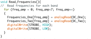
To separate the raw audio signal into seven band, you need a specific function that sends an input to and takes audio data from the two ICs visible on the board. This input is referred to as the Strobe, and it is set to pin 4 on the Arduino board. The audio data is gathered from pins A0 and A1 (left and right) on the Arduino. Each IC is gathering data from one band of frequency at a given time. When a high and low signal are written in succession to the Strobe pin, both ICs switch to passing through data from the next highest band; the ICs start at the lowest band, and will cycle through back to the lowest once switched from the highest band.
With a for loop one can cycle through gathering data from each band, or pick out specific bands for the ICs to measure. An example of this code written by the developer of the spectrum shield, Toni Klopfenstein, demonstrates how to fill two arrays of length 7 with one amplitude measure of each band.
A complete hookup guide written by the spectrums shield's developers can be found here
