Sunlight Alarm
Sunlight Alarm Log
Presentation 1
Contents
Proposal
Overview
Our goal is to create an apparatus that opens your window shades automatically in the morning, providing a more pleasant way to wake up than a loud alarm. Our apparatus will use a stepper motor to open the shades paired with an Arduino and Dual Step Motor Shield. We plan to implement a second stepper motor in order to change the orientation of the slats. The stimuli to open the shades will be based on time as inputted by the user using two buttons attached to the Arduino and. A Raspberry Pi will fetch the current weather and time and send it to the Arduino to be displayed on LCDs, informing the user of the time and weather.
Team Members
- Sam Chai
- Cole Fitzsimmons
- Arnob Dam
- Andrew O'Sullivan (TA)
Objectives
- Build frame and shade
- Program Arduino to accept time input and location imput from user
- Program Raspberry Pi to send time and weather to Arduino
- Use NTP and Wunderground API
- Program Arduino to accept time and weather from Raspberry Pi
- Program Arduino to control motors
- 3D print pieces to attach blind to shade
- Attach motors to frame/shade
- up/down pull-string
- twist bar for slat orientation
Challenges
- Learn how to use Autodesk
- We will use Autodesk to 3D print gears, clamps and other physical parts for the opening/closing function of our device
- Learn how to program Raspberry Pi
- We are using Raspberry Pi instead of Arduino because we will need Raspberry Pi's capability to access the internet. Through the internet, we will have access to and display both time and weather
- Store local city data while Arduino is incapable of storing all of them
- Arduino Uno, which only has 20148 bytes of local memory, is not able to store the names of 1400+ cities as arrays of characters across the United States. It made us to seek new places to store the list of city names. Raspberry Pi would be an ideal location, but that made Arduino more difficult to get access to those data.
- Debouncing all of the buttons seperately
- All buttons are not ideal. They will bounce upward and downward after you pressed; namely, it will be practically be "pressed" multiple times, even if you think you only pressed it once. (For details, please check Contact_bounce). Thus, we need some programming techniques to debounce the buttons -- filtering out the noise after I pressed once.
- Generating enough torque to raise shades
- The motors we have, NEMA 17, is not strong enought to raise the shades all the way up by itself.
- Silencing gears
- When two motors are running at different speeds or not meshing well, great noise will be generated. We have to ensure the smoothness of gear system.
Gantt Chart
Budget
- Raspberry Pi (supplied)
- Arduino (supplied)
- 2 Stepper motors (supplied)
- Arduino LED Backpack (for time) $11.95
- Arduino LCD and Keypad (for weather) $23.95
- 24ft of 2X4s $9.96
- 1 inch #8 wood screws $1.94
- 2 inch #10 multi-purpose screws $7.98
- We would recommend using longer screws such as these.
- 1/2" machine screws $1.18
- Shaft Collar - Clamp (1/4", 2 Pack, w/o shipping fee $11.69
- 1 pack of 4 corner braces $6.28
- 1 pack of straight brackets $4.49
- Probably not necessary
- String $2.97
- Screw Eyes $1.18
- 2 5/16" hex nuts $0.64
- Aluminium rod $4.21
- Shipping (Adafruit) $7.17
- 12V Power Supply $9.99
- Transportation Costs $10
- Blind (30" x 60") $31.09
Total: $140.93
Design and Solutions
Description
Overall Setup
Our Sunlight Alarm consisted of a system of a Raspberry Pi, an Arduino, 2 stepper motors, a 3D printed gear system, an LED display, and an LCD display. The Raspberry Pi fetched the current time and weather data from the internet and sent it to the Arduino. The Arduino then displayed the weather and time on the displays. Using two buttons connected to the Arduino, the user can select a time at which the shade will open. When that time is reached, the Arduino begins to open the shade by running two stepper motors which drive the gear and spool system. Also, user can select their location with five buttons attacthed to LCD shield.
Requesting, cleaning and storing city list from Internet
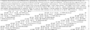
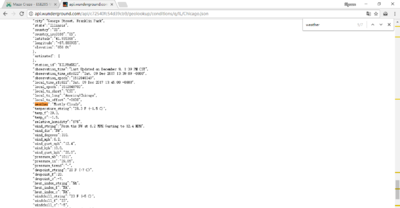
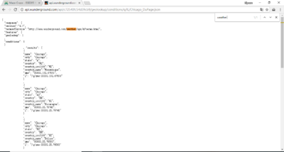
All of our data about weather and time difference comes from wunderground.com which is an online platform with open API for users to access geography data including but not limited to current weather and time zone. It allows users to get data in JSON format if they know the location in State/city format (MO/St._Louis, for example). To get access to the data for all large American cities, we grab the content on US_cities and analyze it in string format. Finally, we store each entry of the city name into a dictionary.
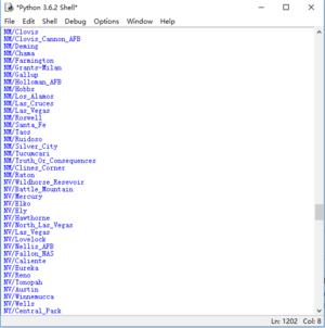
However, the data entries from website are not perfect. Some cities in the list are just observation station which provides no valid weather data. We use try-except function module to catch and delete all the valid entries, pair all the valid entries with number index from 0 to 1391 in dictionary, and save it as a local JSON file (valid_city_entries.json).
Initial index system and communication between Raspberry Pi and Arduino
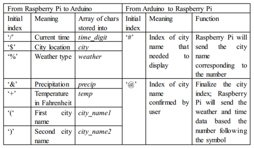
We use the stable and simple serial communication to let Raspberry Pi and Arduino send signals to each other. However, they are exchanging a great amount of information that is all the same data type—bytes. For example, problem arises when Raspberry Pi wants to send time ‘0925’, but Arduino may interpret it as temperature ‘0925.’ To distinguish the meaning of different data sent from same source, we equip our Raspberry Pi-Arduino system with Initial Index System. We add a special symbol before the valid data and a terminator symbol ‘!’to indicate its end. For instance, when raspberry pi is sending the city location data to Arduino, it will send ‘$St. Louis!’ instead of ‘St. Louis’. Then, when Arduino read ‘$’, it understands this is a location data and will store all the bytes before '!' ('S', 't', '.', ' ', 'L', 'o', 'i', 's') into a array of chars named city. Later, Arduino will display the city name based on data in city.
LED Backpack & time display
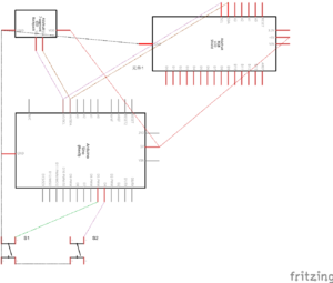
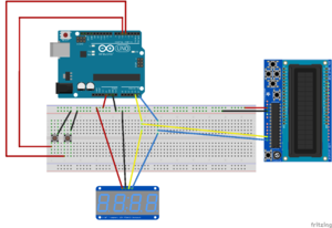
We use the 0.56” 7-Segment Backpack to display current time and allow users to set their waking time (the time shades go up) with two buttons. We followed the tutorial and installed the library. Two pins are connected to Arduino—one confirm pin, another change pin.
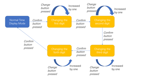
When the confirm button is pressed, our Arduino enters the time setting mode—displaying the previous waking time user sets with first digit blinking. If you user wants to change the blinking digit, he can increase the number of blinking digit by pressing change button. He can move on the next digit by pressing confirm button. This process ends until he moves to the last digit and confirm his choice; then, the Arduino will be back to “normal time display” mode.
After user finishes up his setting of waking time, Arduino will be ready to compare current time and user-set time. As soon as they are the same, Arduino asks the motor to lift the shades up.
LCD shield & weather display
We purchased the RGB LCD Shield and installed its library from adafruit.com. It has a 16*2 LCD display, with which we display the weather and temperature (Fahrenheit) at a specific city. The RGB LCD shield is controlled by Arduino through I2C which is the same protocol as Arduino controls the LED Backpack. Because they are different memory address, they will not run into conflict if we connect them in parallel to Arduino.
The weather inputs from Raspberry Pi are divided into three parts: city name, temperature, and weather type. Based on the Initial Index System we introduced before, Arduino could distinguish the meaning of those data and store them into respective arrays of chars. Whenever the last character of weather type is stored, the Arduino will display all info on screen.
LCD shield & location input
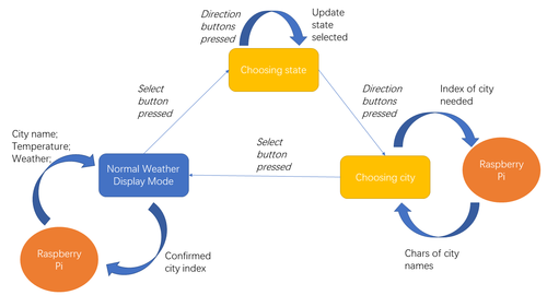
With the five buttons on the RGB LCD Shield, we allow users to select their location from about 1400 cities in U.S. The process is divided into two steps—selecting state and then city. Pressing the select button, user enter the first step. Each state or territory is displayed by its two-character abbreviation; the screen display 10 states (two rows * five columns) at once. User changes their selection by direction buttons, and confirm by select button.
Allowing users to select their cities faces a significant challenge—Arduino does not have enough memory to store all names of cities in the United States. We solve the problem by using the dictionary of city names paired with number index. Whenever Arduino needs to display city names (two in this specific cases, because the LCD sheild can only display two rows of character), it calculates the index of the city based on the state user previously set and sends it to Raspberry Pi. Then Raspberry Pi will send back the two city names Arduino wants to let user literally see them on the 16*2 LCD screen. Similarly, users change their selection by direction buttons, and confirm their ultimate choice by select button. Immediately after user confirms, Raspberry Pi receives the index of that city and returns the weather data and time data back. Since then, Arduino will display the expected time and weather totally based on users input.
Stepper Motors
As described above, when the time set by the user matches the current time, the Arduino sketch is programmed to call on the method that runs the code for the Dual Step Motor Driver Shield, which controlled both stepper motors. Using the Dual Step Motor Driver Shield, it is necessary for two digital pins to be connected between the shield and the Arduino per stepper motor, a Direction pin and a Stepper pin, as well as 5V power and ground. Since we used 2 stepper motors, we needed 4 pins. The shield is designed to use 2 and 3 as one pair, and 6 and 7 as the other. One problem we faced was not generating enough torque to continue opening the shade as it reached the top of the frame. Through some research and experimentation, we found that we could change the torque generated by the stepper motor by changing the code for the motors. By increasing the delay in the method that that runs the motors, we increased torque, but reduced angular velocity. We experimented to find the perfect delay that generated enough torque but maintained a good speed. Another way that we solved this problem was by increasing the voltage to the motors. The data sheet provided us with he information that our stepper motors provide peak torque at 12V, but we were only proving 9V. We ordered a 12V power supply and it helped tremendously. Our final solution to this issue was to turn our larger spool gear with two stepper motors rather than one. By running two stepper motors at a decreased speed with 12V, we were able to open the shade automatically with ease.
Wiring the stepper motors was also a minor challenge. Most stepper motors either have 4 or 6 wires. The Nema 17 stepper motors that we used had 4 wires. Figuring out the proper setup for the wires can be difficult. Finding pairs of wires can be find by randomly holding the ends of 2 wires together and trying to twist the stepper motor by hand. If the stepper motor becomes harder to twist, then those two wires are a pair meaning they will go next to each other when plugged in to the shield. After finding the two pairs of the 4 wires, the easiest thing to do is trial and error. If the stepper doesn't turn properly, just flip the order of the pairs or the individual wires in the pairs. Continue until the stepper works as desired.
During the design of our project, we accidentally broke one of the two ports on the shield. Luckily, we needed our steppers to run in the same direction and speed, so we attached both motors to the same port.
Gear System
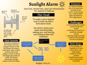
To successfully lift the blinds, a significant pulling force acting on the blind's pulley strings is required. To generate enough force, we are using two stepper motors altogether. We 3D printed a pair of gears to utilize this torque: a smaller gear with 12 teeth directly attached to the stepper motor, and a larger gear with 36 teeth in contact with the smaller gear. The increase in number of teeth coincides with an increase in radius. Because radius and torque are directly proportional, the torque is increased due to the larger radius. But an increase in radius and torque subsequently results in a decrease in speed. A large part of the mechanical problem solving encountered during this project was estimating the ideal balance of torque and speed produced given the maximum voltage supplied by the stepper motor, knowing that a certain threshold in torque is required. Finally, the larger gear is attached to a spool of string, and this string is directly tied to the blind’s pulley strings and acts as a medium to pull up the blinds.
we 3D modeled and printed holder for the two stepper motors. This included taking very precise measurements of the stepper motors so that our holder would be a snug fit. We modeled the holder with screw holes to both attach the motor to the holder and the holder to the frame. Link. We also modeled a box to hold all of the electronics, which we unfortunately were unable to print. Link.
Frame
The frame was built to resemble a window frame. The shade was attached to the inside and top of the frame as a normal shade would. The frame was built from 2x4s, wood screws, and metal brackets. The dimensions of the inside of the window were 30" x 60". We took 3 8ft 2x4s and cut them into 5 pieces: 2 measuring 3', 2 measuring 6'2", and 2 measuring 1'.
New Skills
- Communication between Raspberry Pi and Arduino with one usb cable
- Requesting, analyzing and storing data from website
- Motor control with Arduino
- Installing user library to control I2C devices on Arduino
- 3D modeling gears and spool with Autodesk
- Time management and how to schedule more time for projects
Results
Higher Quality Version of video
We successfully built a a device that:
- displayed the current time, weather conditions, and temperature in a location selected by the user using the buttons on the LCD display
- opened the shade automatically at a specific time selected by the user using the buttons on the breadboard
- changed the color of the LCD display based on the temperature
- automatically unwound the spool to make resetting the device easier
We completed most of our goals with the exception of attaching another stepper motor to the twist bar that controls the orientation of the slats. This minor goal, not necessary to the success of the project, requires one more motor. However, we only have one motor controller which can control two motors at most. While lifting the shades up needs two motors at the same time, we decided it was more important to accomplish the main goals of displaying the weather and raising the blinds.
Repository
Raspberry Pi & Arduino Codes: ESE_205. (main code used for project can be found in window_shades folder)
Stepper Motor Mount
Electronic Box
12 and 36 Teeth Gears


